Illumination device for simulating neon or similar lighting in various colors

a technology of illumination device and neon, which is applied in the direction of lighting support device, lighting and heating apparatus, instruments, etc., can solve the problems of low commercial or practical value of illumination device, inconvenient initial handling, installation and/or replacement, and high cost of neon lighting package and ship, so as to reduce increase and maintain the intensity of light source

Inactive Publication Date: 2007-09-04
ILIGHT TECH INC
View PDF11 Cites 257 Cited by
  • Summary
  • Abstract
  • Description
  • Claims
  • Application Information

AI Technical Summary

Problems solved by technology

Because of the fragility and heavy weight, primarily due to its supporting infrastructure, neon lighting is expensive to package and ship.
Moreover, it is extremely awkward to initially handle, install, and / or replace.
However, the twin attributes of neon lighting, uniformity and brightness, have proven to be difficult obstacles to overcome as such attempts to simulate neon lighting have largely been stymied by the tradeoffs between light distribution to promote the uniformity and brightness.
While it is important that the disadvantages of neon lighting be avoided (for example, weight and fragility), an illumination device would have little commercial or practical value if the proper light uniformity and intensity could not be obtained.
Nevertheless, a problem with illumination devices using leaky waveguides and LEDs, as described and claimed in U.S. Pat. No. 6,592,238, is that the available visible color spectrum is limited by the finite availability of LED colors.

Method used


Image

  • Illumination device for simulating neon or similar lighting in various colors
  • Illumination device for simulating neon or similar lighting in various colors
  • Illumination device for simulating neon or similar lighting in various colors

Examples


Embodiment Construction

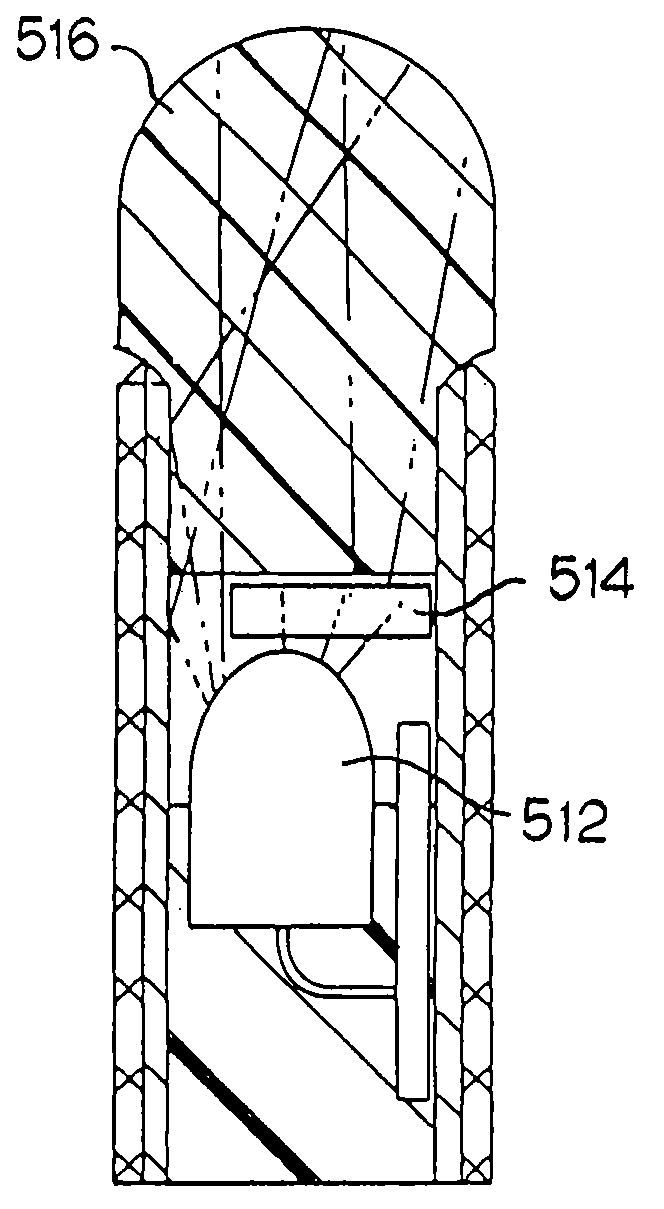
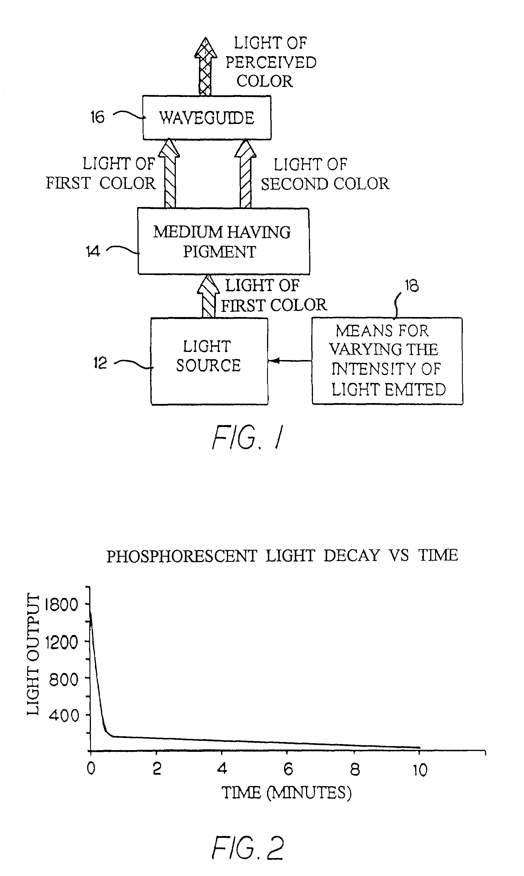
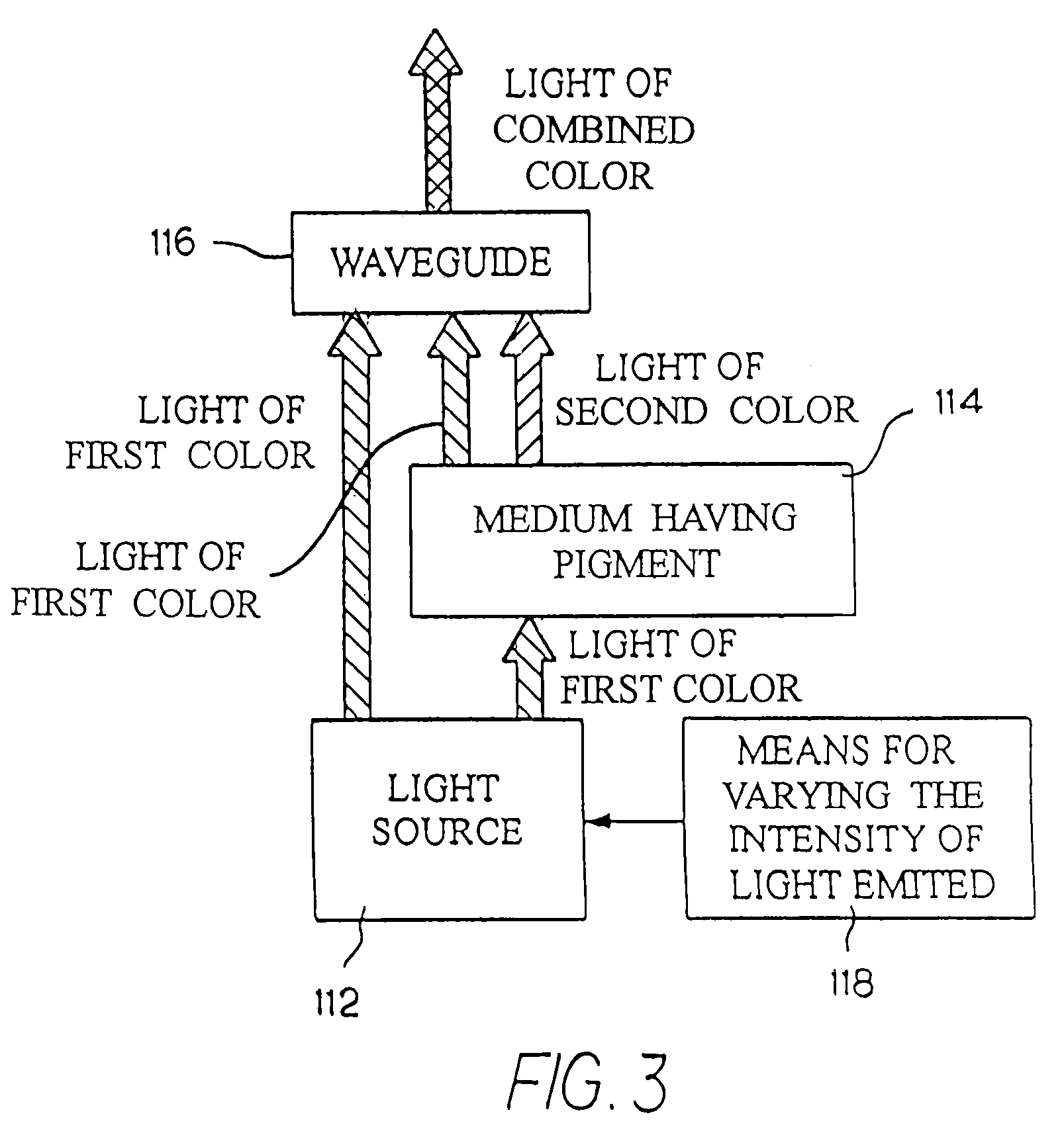
[0027]FIG. 1 is a block diagram of an exemplary illumination device according to the invention. The exemplary illumination device has a light source 12, a light-transmitting medium 14, a waveguide 16, and a means 18 for varying the intensity of the light emitted by light source 12.

[0028]The light source 12 is for emitting light of a first color. Light color, as used herein, is primarily described in terms of the qualities and characteristics of light perceived by an observer. Those of skill in the art recognize various systems for characterizing colors including “hue, brightness and saturation,”“dominant wavelength, luminance, and purity” and others, which, for the purposes herein, are all considered equivalent means for characterizing color. Although it is contemplated that various types of light sources could be utilized to emit the light of the first color, the preferred light source 12 is a plurality of light-emitting diodes (LEDs). Preferably, the LEDs are arranged in a series ...


PUM


Abstract

An illumination device has a light source, a waveguide, and a light-transmitting medium. The light source emits light of a first color. The waveguide has both optical waveguide and light scattering properties. The light-transmitting medium is composed of a matrix of substantially translucent material doped with a pigment, and is positioned between the light source and the waveguide such that a portion of the light emitted by the light source passes around the light-transmitting medium and reaches the waveguide directly, and a portion of the emitted light is received by the light-transmitting medium. The pigment changes a portion of the received light to a light of a second color. The waveguide receives and mixes the light of the first color and the light of the second color, and emits light of a combined color.

Description

CROSS-REFERENCE TO RELATED APPLICATIONS[0001]The present application is a continuation-in-part of U.S. patent application Ser. No. 11 / 025,019, filed Dec. 29, 2004; which claims priority to U.S. Provisional Application Ser. No. 60 / 533,581 filed Dec. 31, 2003 and is a continuation-in-part of U.S. patent application Ser. No. 10 / 455,639 filed on Jun. 5, 2003, now U.S. Pat. No. 7,011,421, issued on Mar. 4, 2006; which is a continuation-in-part of U.S. utility application Ser. No. 09 / 982,705, filed on Oct. 18, 2001, now U.S. Pat. No. 6,592,238, issued on Jul. 15, 2003, the entire disclosures of which are incorporated herein by reference.BACKGROUND OF THE INVENTION[0002]The present invention relates to an illumination device for simulating neon or similar lighting in various colors. The illumination device may also include a means for producing certain color-changing effects.[0003]Neon lighting, which is produced by the electrical stimulation of the electrons in the low-pressure neon gas-f...

Claims


Application Information

Patent Timeline
Patent Type & Authority Patents(United States)
IPC IPC(8): F21V9/16
CPCF21K9/00G02B19/0066G02B19/0028F21Y2101/02F21Y2103/003F21Y2103/10F21Y2115/10
Inventor HULSE, GEORGE R.
Owner ILIGHT TECH INC
Why Eureka
Try Eureka