Magnetic write head having resistive heater coil

a write head and resistive technology, applied in the direction of maintaining the head carrier alignment, recording information storage, instruments, etc., can solve the problems of reducing the areal density that can be achieved, affecting the performance of the write head, and reducing the time for data access

Inactive Publication Date: 2007-10-16
WESTERN DIGITAL TECH INC
View PDF47 Cites 156 Cited by
  • Summary
  • Abstract
  • Description
  • Claims
  • Application Information

AI Technical Summary

Problems solved by technology

The resulting impact can cause the write head to drift off-track, thereby causing a delay in the time for data access.
While such impacts can be avoided by increasing the flying-height distance, larger flying-height distances negatively affect the performance of the write head and reduce the areal density that can be achieved.

Method used


Image

  • Magnetic write head having resistive heater coil
  • Magnetic write head having resistive heater coil
  • Magnetic write head having resistive heater coil

Examples


Embodiment Construction

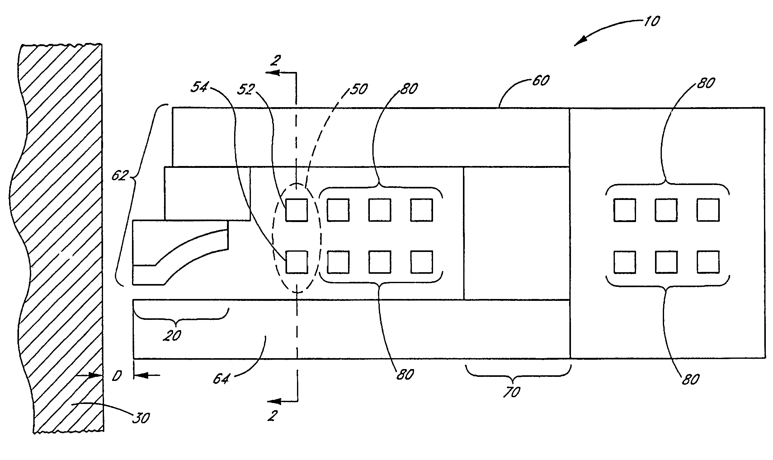
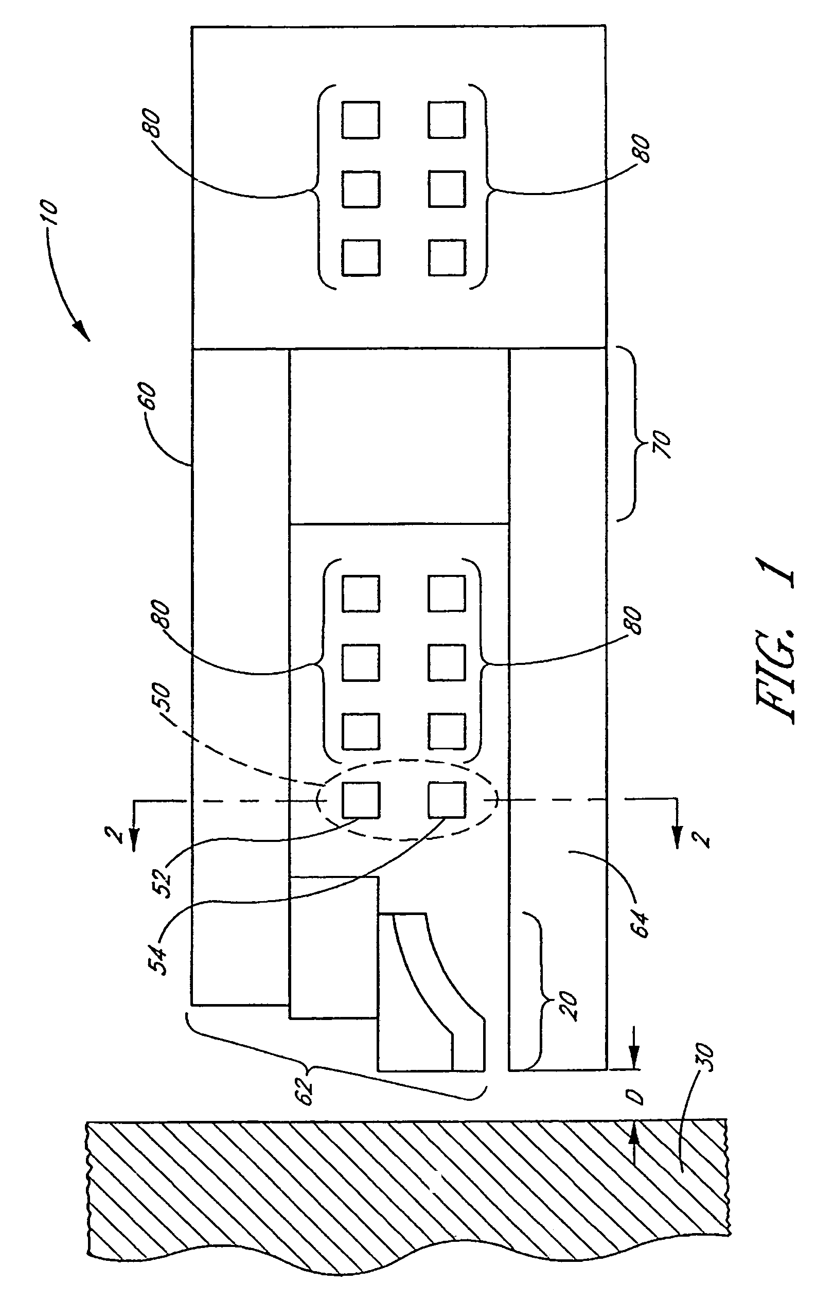
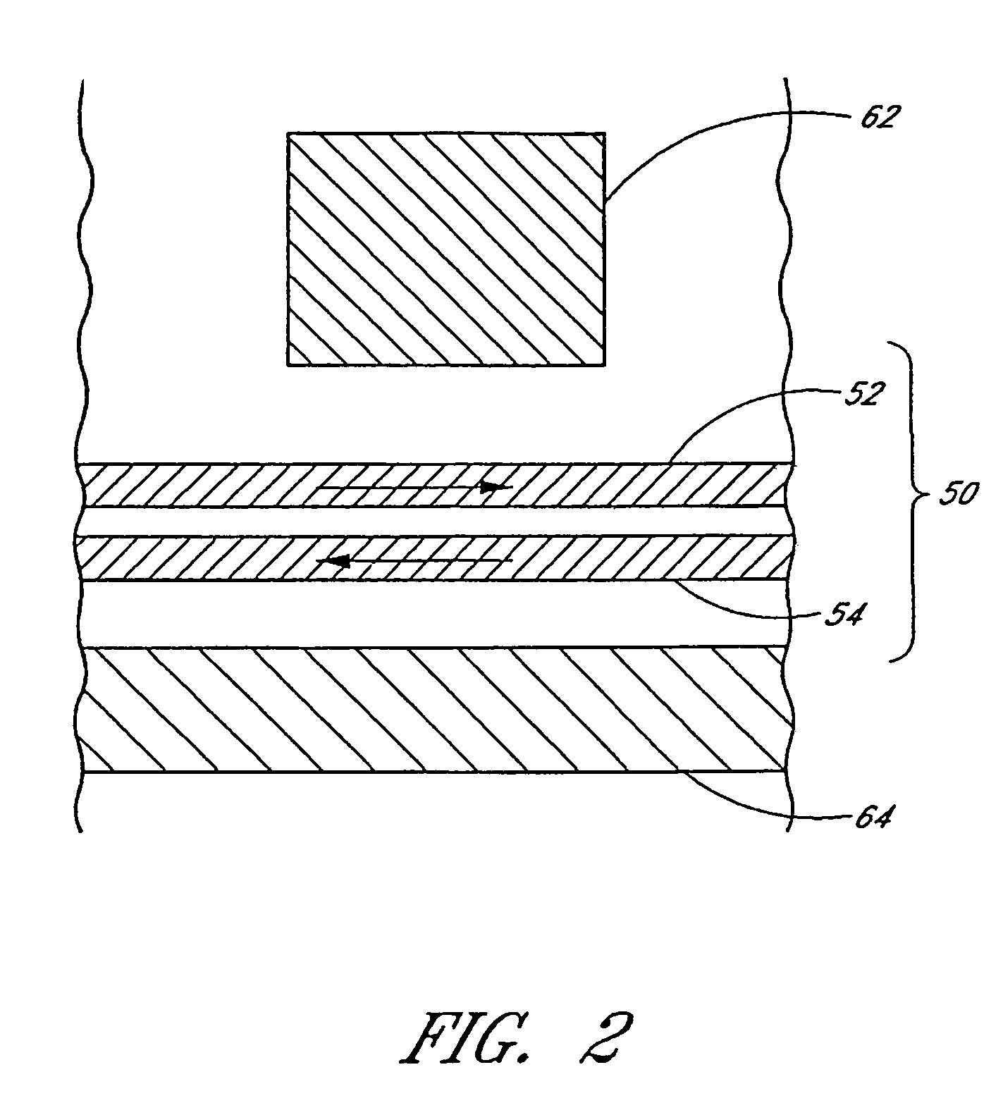
[0018]FIG. 1 schematically illustrates a cross-sectional view of an exemplary magnetic write head 10 in accordance with embodiments described herein. The write head 10 comprises a gap region 20 configured to generate a magnetic field at a magnetic medium 30. The gap region 20 and the magnetic medium 30 are separated by a flying-height distance D that depends on a temperature of the gap region 20. The write head 10 further comprises a resistive heater 50 comprising a first conductor segment 52 located in a first position in proximity to the gap region 20. The first conductor segment 52 has a first electrical resistance and is configured to allow a first electric current to flow therethrough. The first electric current generates heat in the gap region 20 and generates a first magnetic field. The resistive heater 50 further comprises a second conductor segment 54 located in a second position in proximity to the gap region 20. The second conductor segment 54 has a second electrical resi...


PUM

PropertyMeasurementUnit
electrical resistancesaaaaaaaaaa

Abstract

A magnetic write head includes a magnetic yoke having a first pole and a second pole. The first pole and the second pole each terminate at an air bearing surface. The first pole is magnetically coupled to the second pole in a backgap region. The magnetic write head further includes a electrically conductive write coil magnetically coupled to the magnetic yoke. The magnetic write head further includes a resistive heater coil having a first coil turn and a second coil turn. The heater coil is electrically isolated from the write coil. At least a portion of the first coil turn is between the first pole and the second pole and between the air bearing surface and the backgap region. At least a portion of the second coil turn is between the first pole and the second pole and between the air bearing surface and the backgap region. The portion of the first coil turn overlaps the portion of the second coil turn.

Description

RELATED APPLICATIONS[0001]This application is a continuation of U.S. patent application Ser. No. 10 / 856,403, filed May 28, 2004, now U.S. Pat. No. 7,092,195 which is incorporated in its entirety by reference herein.BACKGROUND OF THE INVENTION[0002]1. Field of the Invention[0003]This application relates generally to magnetic write heads for magnetic recording, and more specifically to apparatuses and methods for controlling the flying-height distance between the write head and the magnetic medium.[0004]2. Description of the Related Art[0005]The areal density of magnetic recording depends in part on the flying-height distance between the magnetic medium and the air-bearing surface (“ABS”) of the magnetic write head. As areal densities continue to increase, the flying-height distance continues to decrease. In addition, the flying-height distances among different write heads .have variations (e.g., due to variations in the manufacturing process). The ranges of these variations have rema...

Claims


Application Information

Patent Timeline
Patent Type & Authority Patents(United States)
IPC IPC(8): G11B5/17G11B21/02G11B5/56
CPCG11B5/6064G11B5/60
Inventor LIU, FRANCIS H.STOEV, KROUM S.KROUNBI, MOHAMAD T.
Owner WESTERN DIGITAL TECH INC
Why Eureka
Try Eureka