Clip-on with flexible and expandable bridge member

a bridge member and flexible technology, applied in the field of clip-on sunglasses, can solve the problems of obstructing the view of users, scratching the lenses, and the disadvantages of the clamp-type mechanism,

Inactive Publication Date: 2007-10-23
OPSALES
View PDF13 Cites 34 Cited by
  • Summary
  • Abstract
  • Description
  • Claims
  • Application Information

AI Technical Summary

Problems solved by technology

However, clamp-type mechanisms have their disadvantages.
In order to secure the clip-on sunglasses, the prongs must clamp tightly to the lenses, potentially scratching the lenses.
The mechanism may partially obstruct the view of the user.
Moreover, clamp-type mechanisms have several inter-engaging parts which must be fabricated precisely and assembled, making the mechanism relatively expensive and sometimes unreliable.
One problem inherent in the Lockwood type spring bridge mechanism is that the coil spring is exposed.
Aside from being unsightly, this is undesirable because bits of solid debris and other particulate foreign matter can lodge between the coils and jam the mechanism or distort the spring.
Liquid, such as rain or sweat, can enter the mechanism resulting in rusting or deterioration of the parts.
Further, the skin, hair and eyebrows of the user are not protected from being pinched by the exposed spring.
However, in a configurations such as shown in U.S. Pat. No. 6,685,314 or in U.S. Pat. No. 6,869,179, where the bridge mechanism of the clip-on sunglasses is designed to align with the bridge of the eyeglasses upon which the sunglasses are mounted, an eyeglass bridge that protrudes out of the plane of the eyeglass lenses will interfere with the bridge mechanism of the clip-on sunglasses and prevent the clip-on from being properly mounted on the eyeglasses.
This is because the bridge mechanism of the clip-on sunglasses cannot bend or flex to accommodate the protruding bridge of the eyeglasses.
Since many, if not most, eyeglasses have bridges that at least partially extend out of the plane of the lenses, and none of the known enclosed spring bridge mechanisms is bendable or flexible, none can be used in situations in which the enclosed spring bridge mechanism must align with the protruding bridge of the eyeglasses.

Method used


Image

  • Clip-on with flexible and expandable bridge member
  • Clip-on with flexible and expandable bridge member
  • Clip-on with flexible and expandable bridge member

Examples


Embodiment Construction

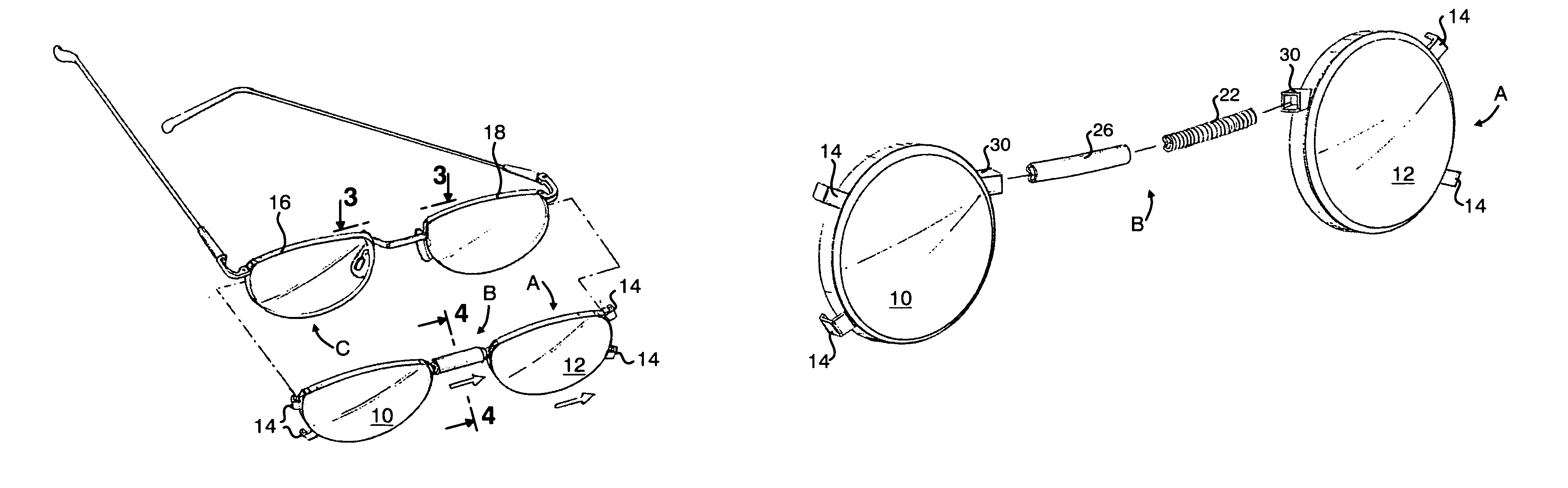
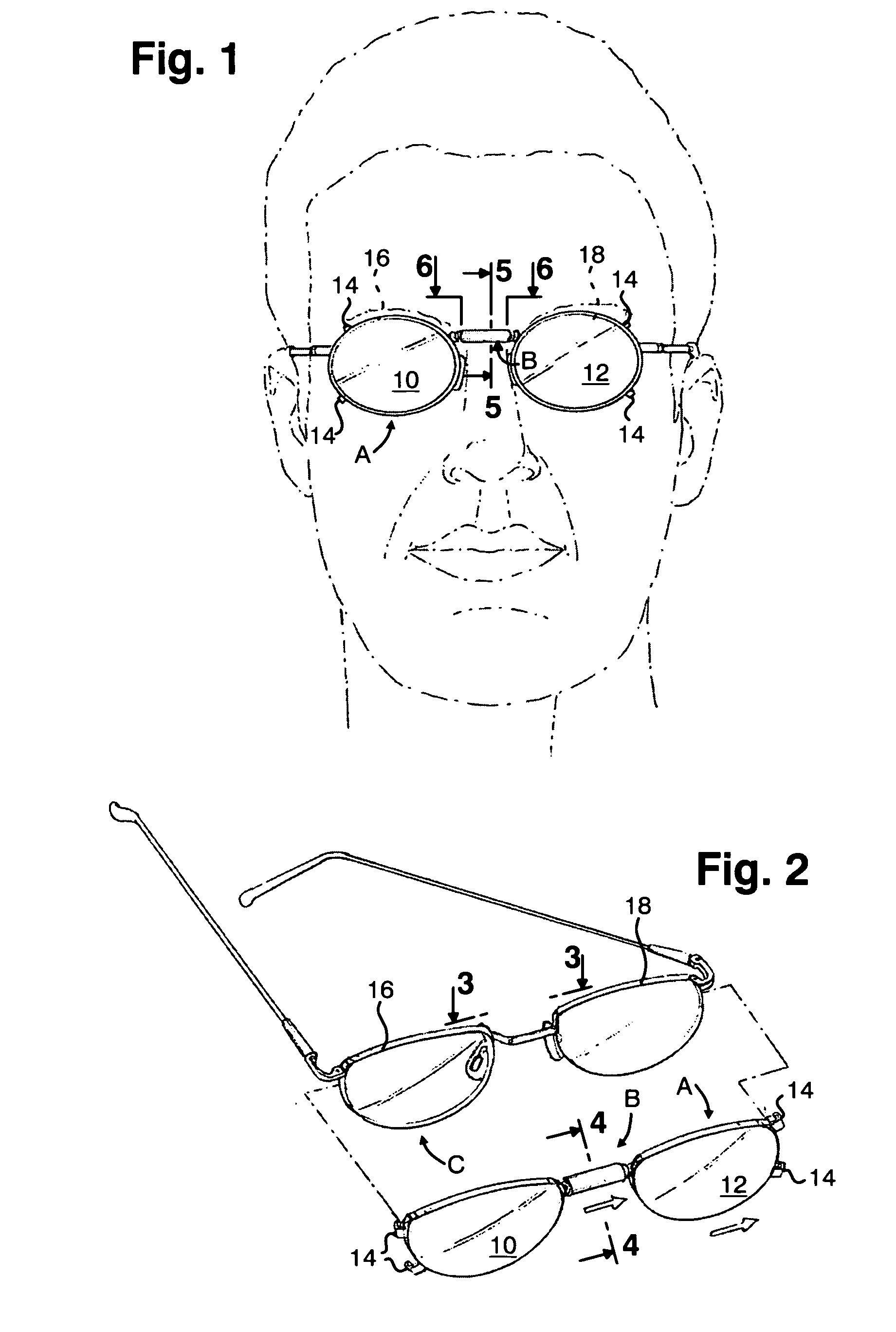
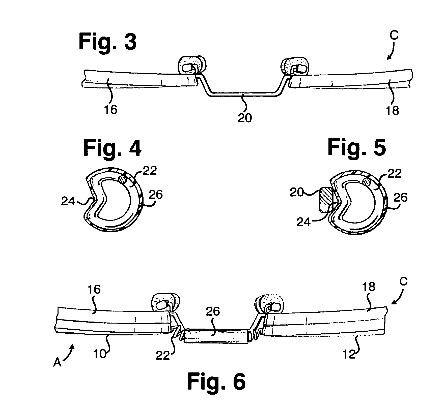
[0049]As seen in FIGS. 1 and 2, the present invention relates to clip-on sunglasses, generally designated A, consisting of lens sections 10 and 12 connected together by a bridge member, generally designated B. Bridge member B is expandable to permit the lens sections 10, 12 to be moved between a proximate position, as shown in FIG. 1, and a remote position, as shown in FIG. 2, in the direction of the arrows of FIG. 2. Bridge member B urges the lens sections 10, 12 toward the proximate position.

[0050]Each of the lens sections 10, 12 has a pair of spaced, eyeglass engaging prongs 14 situated along the outer portion of the rim. Prongs 14 are preferably generally “L” shaped and extend rearwardly from sunglasses A. Prongs 14 are adapted to engage the rims of the lens sections 16, 18 of eyeglasses, generally designated C, when the lens sections 10, 12 of sunglasses A are moved apart, from the proximate position to the remote position, to expand bridge member B. Sunglasses B are then situa...


PUM


Abstract

The expandable and flexible bridge member is adapted for use a a part of clip-on sunglasses. It permits the sunglasses to be mounted on any eyeglasses, including those with a protruding bridge, with the bridge member of the sunglasses in alignment with the bridge of the eyeglasses. The bridge member can take the form of a uniquely shaped spring with a shrink wrapped plastic sleeve or one or more strips of elastic or rubber-like material. The bridge member is provided with a bridge engaging capability so that proper alignment is maintained with the eyeglasses bridge. The bridge engaging structure may take the form of a recess or a hook.

Description

CROSS-REFERENCE TO RELATED APPLICATIONS[0001]Not ApplicableSTATEMENT REGARDING FEDERALLY SPONSORED RESEARCH OR DEVELOPMENT[0002]Not ApplicableREFERENCE TO A “SEQUENCE LISTING”, A TABLE, OR A COMPUTER PROGRAM LISTING APPENDIX SUBMITTED ON COMPACT DISC[0003]Not ApplicableBACKGROUND OF THE INVENTION[0004]1. Field of the Invention[0005]The present invention relates to clip-on sunglasses and more particularly to an improved bridge member for clip-on sunglasses that enables the sunglasses to be mounted on eyeglasses in which the bridge of eyeglasses lies at least partially out of the plane of the eyeglass lenses, with the bridge member of the sunglasses in alignment with the protruding bridge of the eyeglasses.[0006]2. Description of Prior Art Including Information Disclosed Under 37 CFR 1.97 and 1.98[0007]Clip-on sunglasses consist of a metal or plastic frame that carries a pair of light attenuating plastic or glass lenses. A mechanism is provided to removably mount the clip-on sunglasse...

Claims


Application Information

Patent Timeline
Patent Type & Authority Patents(United States)
IPC IPC(8): G02C9/00
CPCG02C5/04G02C9/00G02C5/06
Inventor FRIEDMAN, DEAN
Owner OPSALES
Why Eureka
Try Eureka