Plug-socket assembly

a plug socket and socket technology, applied in the direction of rod connection, coupling device connection, mechanical apparatus, etc., can solve the problem of the plug coming out of the socket undesired

Active Publication Date: 2008-02-19
NITTO KOHKI CO LTD
View PDF25 Cites 22 Cited by
  • Summary
  • Abstract
  • Description
  • Claims
  • Application Information

AI Technical Summary

Benefits of technology

[0004]An object of the present invention is to provide a plug-socket assembly in which the plug cannot come out of the socket even if an excessive external pulling force is applied to the plug.
[0008]In the plug-socket assembly according to the present invention, if an excessive force is applied to the plug so as to pull it out of the socket, the locking element is moved radially outward by the slant rear surface of the forward end head portion of the plug, causing the locking element-actuating member to move against the urging force of the resilient member. Even if such occurs, when the locking element reaches a position where it engages the fourth portion of the locking element sliding surface, there is no longer any force from the locking element that causes the locking element-actuating member to move in the axial direction. Accordingly, the radially outward movement of the locking element is blocked, and thus the plug is prevented from being undesirably pulled out.
[0010]Preferably, the slope between the first portion and the fourth portion is less steep than the slope between the fourth portion and the second portion. The reason for this is as follows. The slope between the first portion and the fourth portion is preferably minimized in order to maximize the radially inward force transmitted from the resilient member to the locking element through the locking element-actuating member to thereby increase the force for drawing the plug into the plug insertion hole. On the other hand, the slope between the fourth portion and the second portion is preferably made steep in order that a small axial displacement of the locking element-actuating member shall allow the locking element to be displaced radially outward to a considerable extent (i.e. in order to minimize the axial length of the locking element-actuating member).
[0011]In order to allow the plug to be inserted into the plug insertion hole without moving the locking element-actuating member in the axial direction, balls that are displaceable radially outward by the forward end head portion of the plug may be used to be pressed against the slant surface between the fourth portion and the second portion to move the locking element-actuating member in the axial direction, as will be described later. In this regard also, the slope between the fourth portion and the second portion should be made steep to minimize the force required to insert the plug.
[0018]Preferably, the socket body is provided with a flange extending radially outward so that the forward end of the locking element-actuating member, as viewed in the urging direction in which it is urged by the resilient member, engages the flange when the plug is not inserted. The reason for this arrangement is to prevent the locking element-actuating member from hitting the first balls or the second balls when the locking element-actuating member is released after it has been pulled back by a manual operation and then pushed back by the resilient member.
[0019]In the plug-socket assembly according to the present invention, when the plug is inserted into the socket, the locking element engages the slant rear surface of the forward end head portion of the plug, and at this time, the slanted locking element sliding surface of the locking element-actuating member is engaged with the locking element, and the pressing force of a resilient member, e.g. a spring, is applied to the locking element, thereby applying drawing force to the plug in the plug insertion direction. By so doing, the plug is locked to the socket without play. In addition, even if an excessive pulling force is applied to the plug, the locking element sliding surface will not be displaced to such an extent as to release the locking element, which might otherwise occur in the prior art, but allows the locking element to remain in the engaging position with the forward end head portion of the plug, whereby the plug can be prevented from being pulled out of the socket.

Problems solved by technology

In this type of fastening device, however, if an excessive pulling force is applied to the plug, the slant surface of the plug acts to displace the locking element radially outward, which may lead to a situation that the plug undesirably comes out of the socket.

Method used


Image

  • Plug-socket assembly
  • Plug-socket assembly
  • Plug-socket assembly

Examples


first embodiment

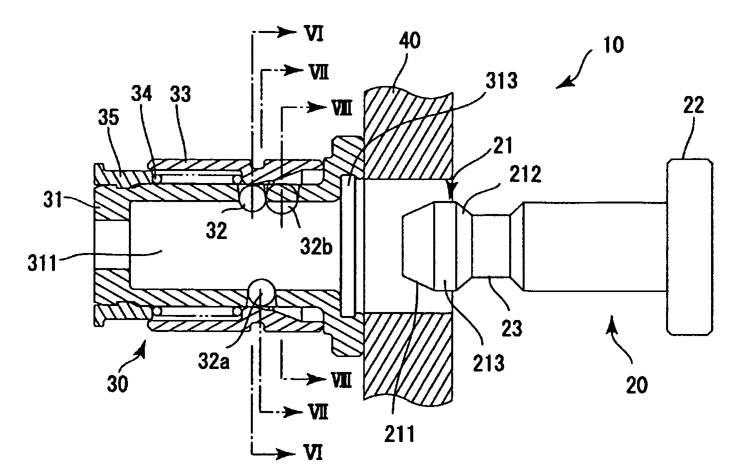
[0039]the plug-socket assembly according to the present invention will be explained with reference to FIGS. 1 to 4A. In the following description, the term “axial direction” means a “direction along the longitudinal axis of the plug insertion hole” or a direction parallel thereto, and the term “radial direction” means a “direction extending radially” from the “axial direction”.

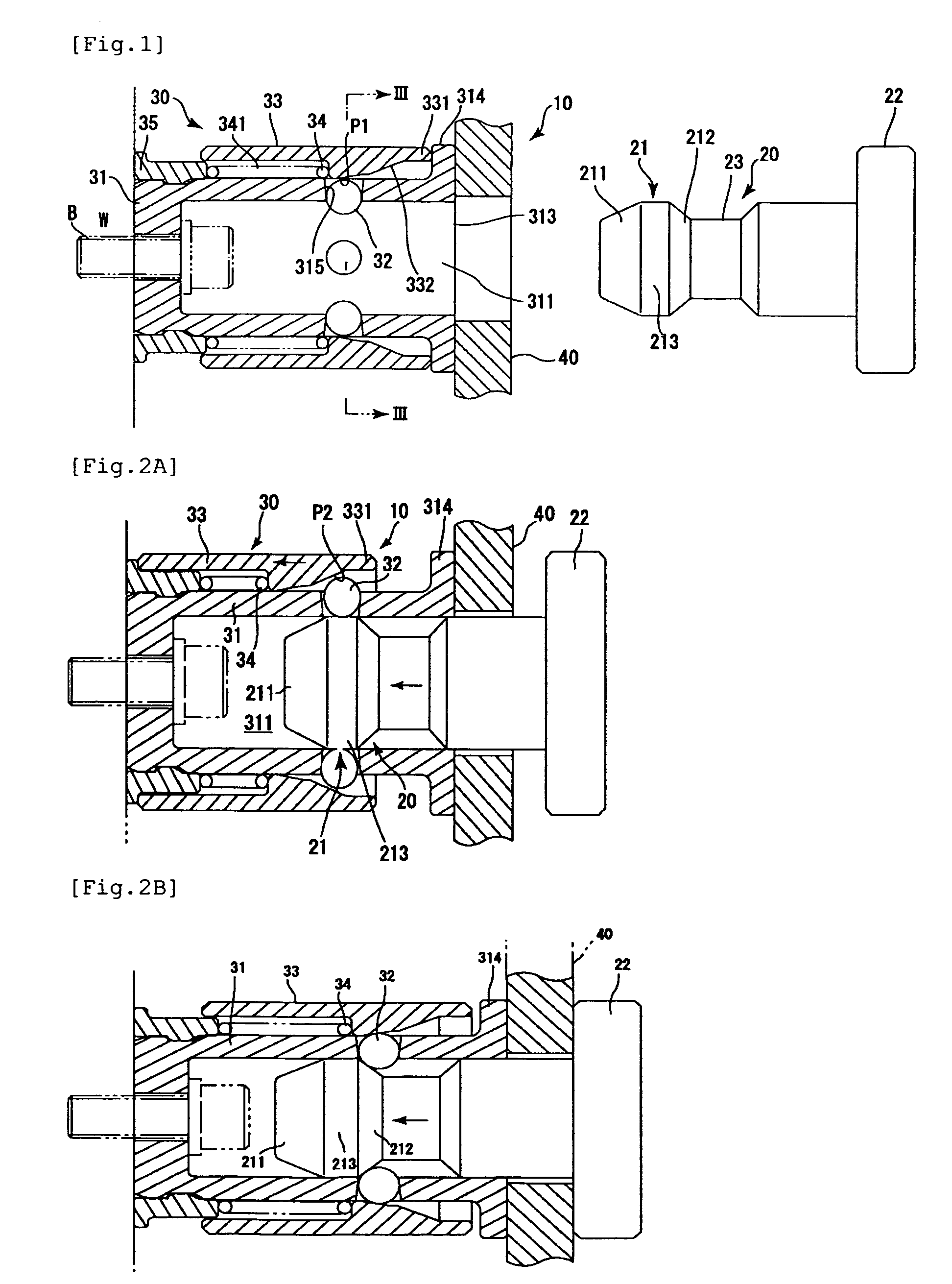
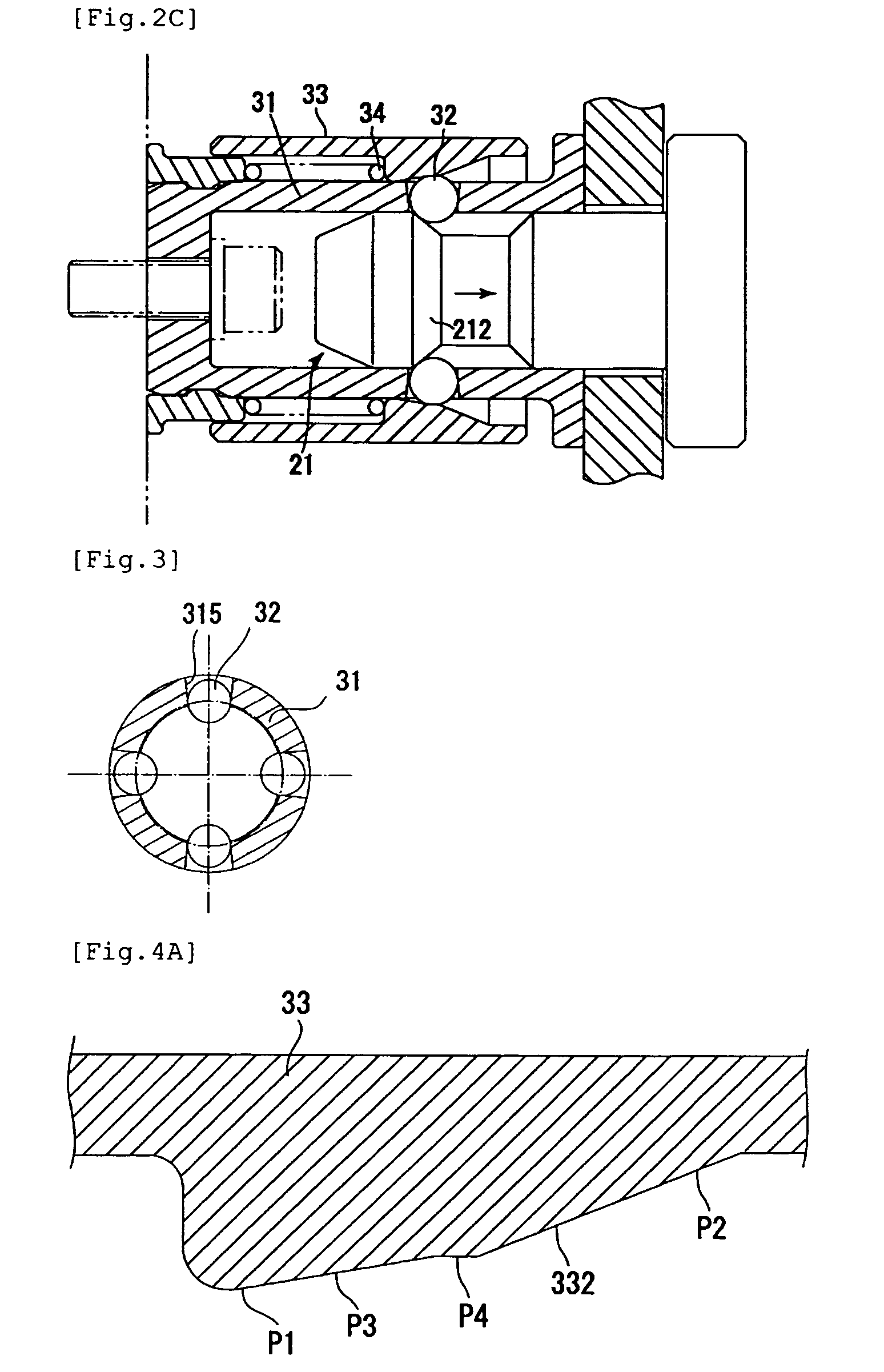
[0040]FIG. 1 is a longitudinal sectional view of a first embodiment of a plug-socket assembly 10. FIGS. 2A to 2C are views for explaining the operation of the plug-socket assembly 10. FIG. 3 is a schematic cross-sectional view as seen from the line III-III in FIG. 1. FIG. 4A is a fragmentary longitudinal sectional view of a sleeve.

[0041]As shown in FIG. 1, the plug-socket assembly 10 includes a plug 20 and a socket 30 that receives and secures the plug 20. The socket 30 has a socket body 31 having a plug insertion hole 311, and a locking element (assuming the form of balls in the illustrated example; hereinaft...

second embodiment

[0053]A second embodiment of the plug-socket according to the present invention will be explained with reference to FIGS. 5 to 9. FIG. 5 is a longitudinal sectional view of the plug-socket assembly 10. FIG. 6 is a schematic cross-sectional view as seen from the line VI-VI in FIG. 5. FIG. 7 is a schematic cross-sectional view as seen from the line VII-VII in FIG. 5. FIG. 8 is a schematic cross-sectional view as seen from the line VIII-VIII in FIG. 5. FIG. 9 is a view for explaining the operation of the plug-socket assembly 10 according to the second embodiment.

[0054]The basic arrangement of the plug-socket assembly 10 is substantially the same as that of the foregoing first embodiment. Therefore, only the points in which the second embodiment differs from the first embodiment will be explained below.

[0055]In the plug-socket assembly 10 according to the second embodiment, the socket body 31 has, as shown in FIGS. 5 to 7 and 9, first and second sleeve-actuating balls 32a and 32b (see F...


PUM


Abstract

An object of the present invention is to provide a plug / socket assembly in which the plug will never pull out of the socket even if an excessive pull-out force is applied to the plug. A plug / socket assembly (10) comprises a plug (20) and a socket (30) for receiving and fixing the plug (20) therein. The socket (30) includes a socket main body (31) having a plug insertion hole (311), balls (32) which are provided with the socket main body (31) in a radially displaceable manner with respect to the plug insertion hole (311), a sleeve (33) which is mounted over the outer surface of the socket main body (31) and is displaceable along the axial direction of the plug insertion hole (311), and a compression spring (34) for urging the sleeve (33) along the axial direction toward the inlet port (313) of the plug insertion hole. The inner surface of the sleeve is provided with a slide surface (332). The slide surface has first to fourth regions (P1-P4). The fourth region (P4) is shaped such that with an external pull-out force being applied to the plug, even if the balls apply a radially outward force to the slide surface, no leftward force to push back the sleeve will be produced.

Description

[0001]This application is a continuation of PCT / JP2005 / 009649, filed May 26, 2005, which claims priority to Japanese Application No. 2004-171883, filed Jun. 9, 2004. The entire contents of these applications are incorporated herein by reference.FIELD OF THE INVENTION[0002]The present invention relates to a plug-socket assembly including a plug and a socket that receives and secures the plug. More particularly, the present invention relates to a plug-socket assembly suitable for use as a device for fastening an article.BACKGROUND OF THE INVENTION[0003]There is known a fastening device in which a socket is fixed to a wall, for example, and a plug is inserted into the socket and locked therein, thereby attaching to the wall a desired article such as a cover of lighting equipment previously attached to the plug. In order that the plug and the socket shall be surely connected together without play, the rear surface of the forward end head portion of the plug is formed into a slant surfac...

Claims


Application Information

Patent Timeline
Patent Type & Authority Patents(United States)
IPC IPC(8): H01R4/50F16B21/07F16B7/20F16B21/00F16B21/16
CPCF16B21/165
Inventor TSUJITA, SATOSHI
Owner NITTO KOHKI CO LTD
Why Eureka
Try Eureka