
Combination mailer and confirmation post card assembly

a mailer and confirmation technology, applied in the field of postal forms, can solve the problems of manual feeding of the same form a second pass through the printer, the inability to batch, and the significant effort of preparing and distributing these notices, so as to achieve the effect of not increasing the risk of jamming

Inactive Publication Date: 2008-03-11
LASER SUBSTRATES
View PDF9 Cites 6 Cited by
  • Summary
  • Abstract
  • Description
  • Claims
  • Application Information

AI Technical Summary

Benefits of technology

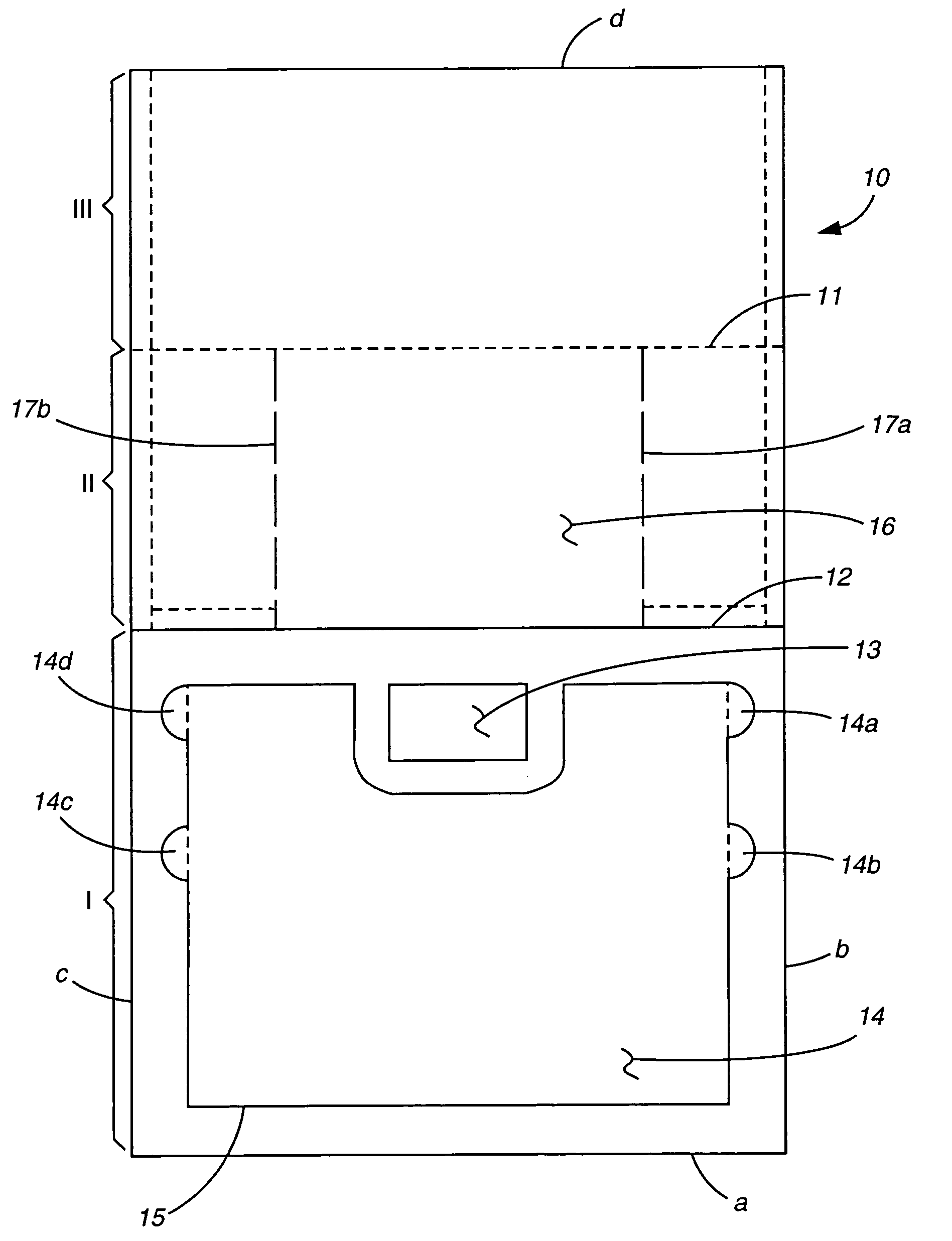
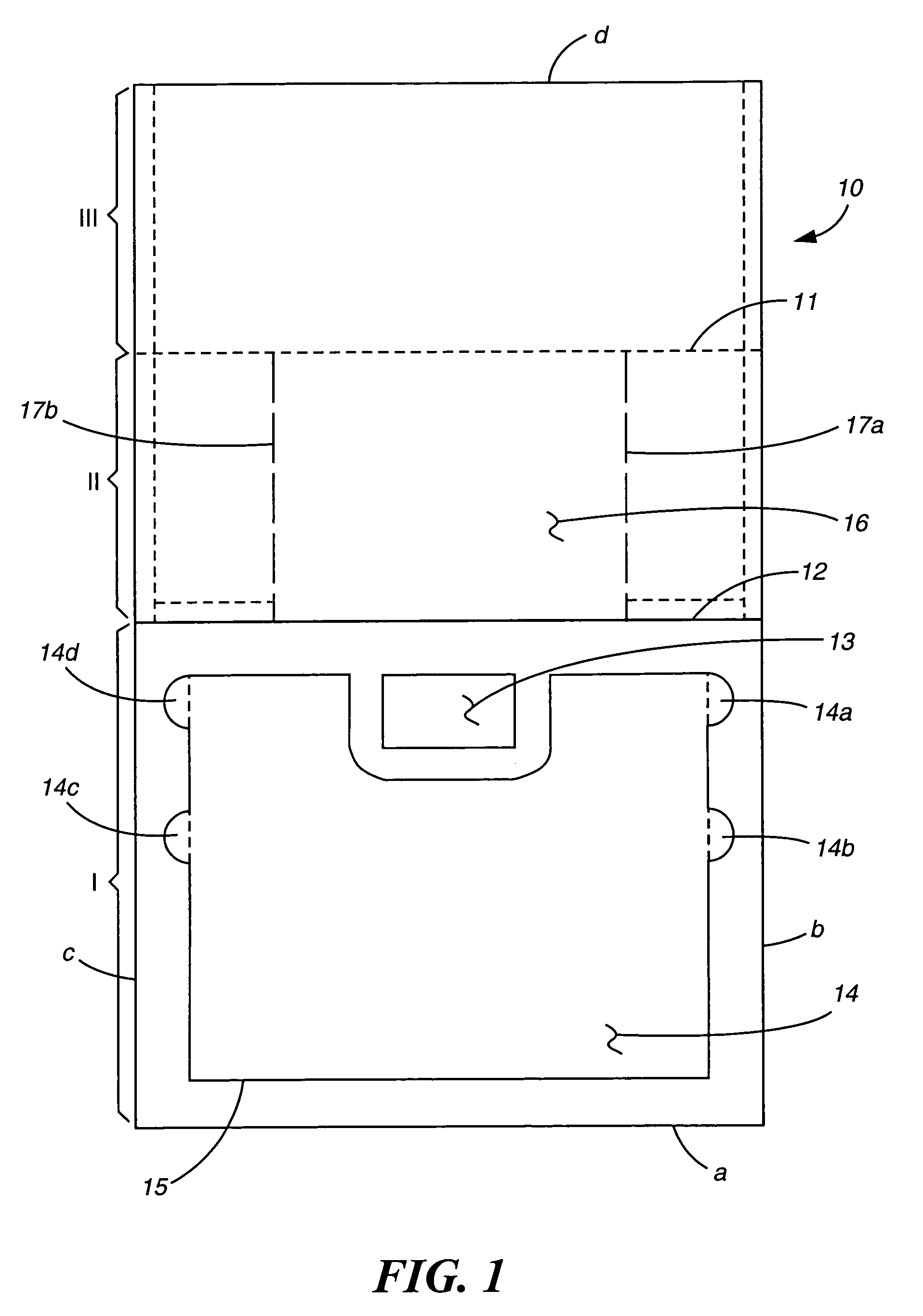
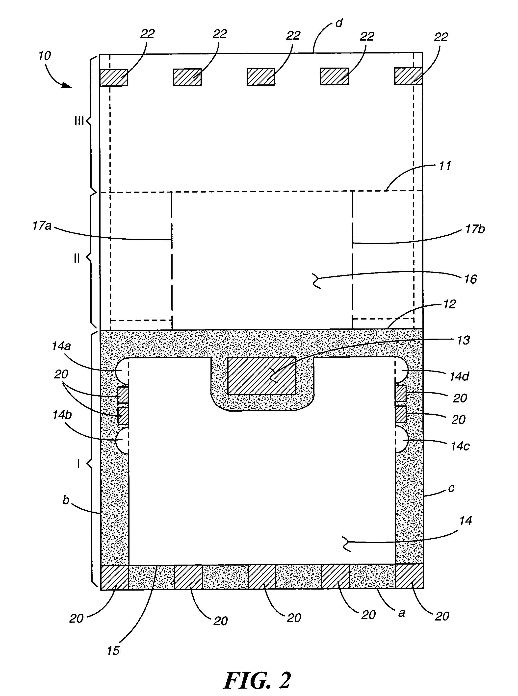
[0005]The subject invention concerns an assembly constructed of at least two plies affixed together to form a single, two-ply sheet. This sheet comprises a plurality of perforations or score lines dividing the sheet into distinct sections from which certain portions can be formed into particular useful postal items. Advantageously, the subject postal form assembly has a thickness corresponding to that of standard paper whereby the form can be printed on a conventional non-impact printer without increased risk of jamming in the feeder mechanism of the printer. A further advantage to the subject assembly is that it can be folded in a manner to provide a standard post card having a thickness as required by the United States Postal Service (USPS).

Problems solved by technology

In most organizations, preparing and distributing these notices represent a significant effort.
Most commonly used non-impact printers are simplex printers and are therefore limited to printing only on a single face of one sheet of paper at a given time.
While it is possible to turn the paper over for a second pass through the printer to print on both faces, automated devices which accomplish this turnover function are not commonly available with conventional non-impact printers used in most offices.
Moreover, manually feeding the same form a second pass through the printer does not allow for batching, whereby a large number of blank forms are placed in a paper feeding tray and all forms are produced at one time.
Further, most pressure-seal documents require specialized folder / sealer equipment which is both expensive and cumbersome to use.
In addition, non-impact printers may be limited in their capacity to handle paper stock that is thicker than conventional paper stock, which typically has a thickness of about 0.003 to 0.0035 inches.
Accordingly, using a conventional non-impact printer to print post cards which meet such USPS requirements may cause jamming of the paper feeder mechanism or other paper handling problems.
Thus, documents designed to be sent through the mail as postcards, may not be capable of being automatically generated with conventional office non-impact printers.

Method used


Image

  • Combination mailer and confirmation post card assembly
  • Combination mailer and confirmation post card assembly
  • Combination mailer and confirmation post card assembly

Examples


Embodiment Construction

[0021]The subject invention concerns a postal form assembly constructed of at least two plies affixed together using, preferably, a conventional adhesive to form a single or unitary multi-ply sheet. The multi-ply sheet provides an outgoing mailer or envelope portion and a plurality of sections which can provide additional mail item portions, e.g., a correspondence portion, a post card portion, and in certain embodiments, a sender's receipt portion.

[0022]The sections are formed in the assembly by perforations or score lines through one or more of the plies. The perforations are formed in the sheet to facilitate separating one section of the assembly from another section. Typically, each section comprises one or more mail item portions which are further separable from its corresponding section by employing die-cuts defining the portion.

[0023]As would be readily understood, the manufacture of a preferred embodiment of the assembly comprises providing a sheet of paper or other printable...


PUM


Abstract

A form assembly formed by front and back plies for creating a postcard having printing on both faces from a single pass through a non-impact printing device.

Description

BACKGROUND OF THE INVENTION[0001]This invention relates to postal forms which, having an image placed on a single face thereof by a single pass through a non-impact printer, can be folded or manipulated in a particular way to provide images on two faces of the form. The subject invention, more particularly, relates to postal forms which can provide a plurality of postal forms useful for specialized postal services, e.g., Certified mail.[0002]Many types of specialized business forms, including postal forms, are made for use with non-impact printers such as laser or ink-jet printing devices. Non-impact printers are being increasingly used to provide a fast, economical, and convenient method of printing data or other information stored in computer system databases. For example, notices to business customers or debtors can be generated automatically from databases containing retrievable information specific for that customer or debtor. Because such notices often carry legal significance...

Claims


Application Information

Patent Timeline
Patent Type & Authority Patents(United States)
IPC IPC(8): B42D15/00B65D27/00H04L12/56H04L12/14H04L29/12H04M3/00H04M3/42H04M3/53H04M3/56H04M7/00H04M15/00
CPCH04L12/14H04L51/18H04L12/1414H04L12/1428H04L12/1464H04L12/1471H04L29/06H04L29/12122H04L29/1216H04L61/1547H04L61/157H04M3/42221H04M3/56H04M7/0009H04M7/003H04L65/1043H04L65/1069H04L12/1403H04L29/06027H04M3/42H04M3/42008H04M3/5322H04M7/0006H04M15/00H04M2215/01H04M7/128H04L61/4547H04L61/4557H04L9/40H04L65/1101
Inventor FABEL, WARREN M.CORTEZ, JOSE B.
Owner LASER SUBSTRATES
Learn More