Electromagnet-assisted ventilation cover for an electronic equipment enclosure

a technology of electronic equipment and ventilation cover, which is applied in the direction of electrical apparatus, electrical apparatus casing/cabinet/drawer, cooling/ventilation/heating modification, etc., can solve the problems of existing exhaust vent actuator, relatively high cost and complexity, and achieve the effect of simple and inexpensive implementation

Active Publication Date: 2008-03-18
VERTIV CORP
View PDF25 Cites 56 Cited by
  • Summary
  • Abstract
  • Description
  • Claims
  • Application Information

AI Technical Summary

Benefits of technology

[0005]The inventor hereof has succeeded at designing ventilation assemblies for electronic equipment enclosures that do not require expensive actuators and that are relatively simply and inexpensive to implement.

Problems solved by technology

As recognized by the inventor hereof, there are several disadvantages to existing exhaust vent actuators, including their relatively high cost and complexity.

Method used


Image

  • Electromagnet-assisted ventilation cover for an electronic equipment enclosure
  • Electromagnet-assisted ventilation cover for an electronic equipment enclosure
  • Electromagnet-assisted ventilation cover for an electronic equipment enclosure

Examples


Embodiment Construction

[0015]The following description of exemplary embodiments is merely exemplary in nature and is in no way intended to limit the scope of the present invention, its applications, or uses.

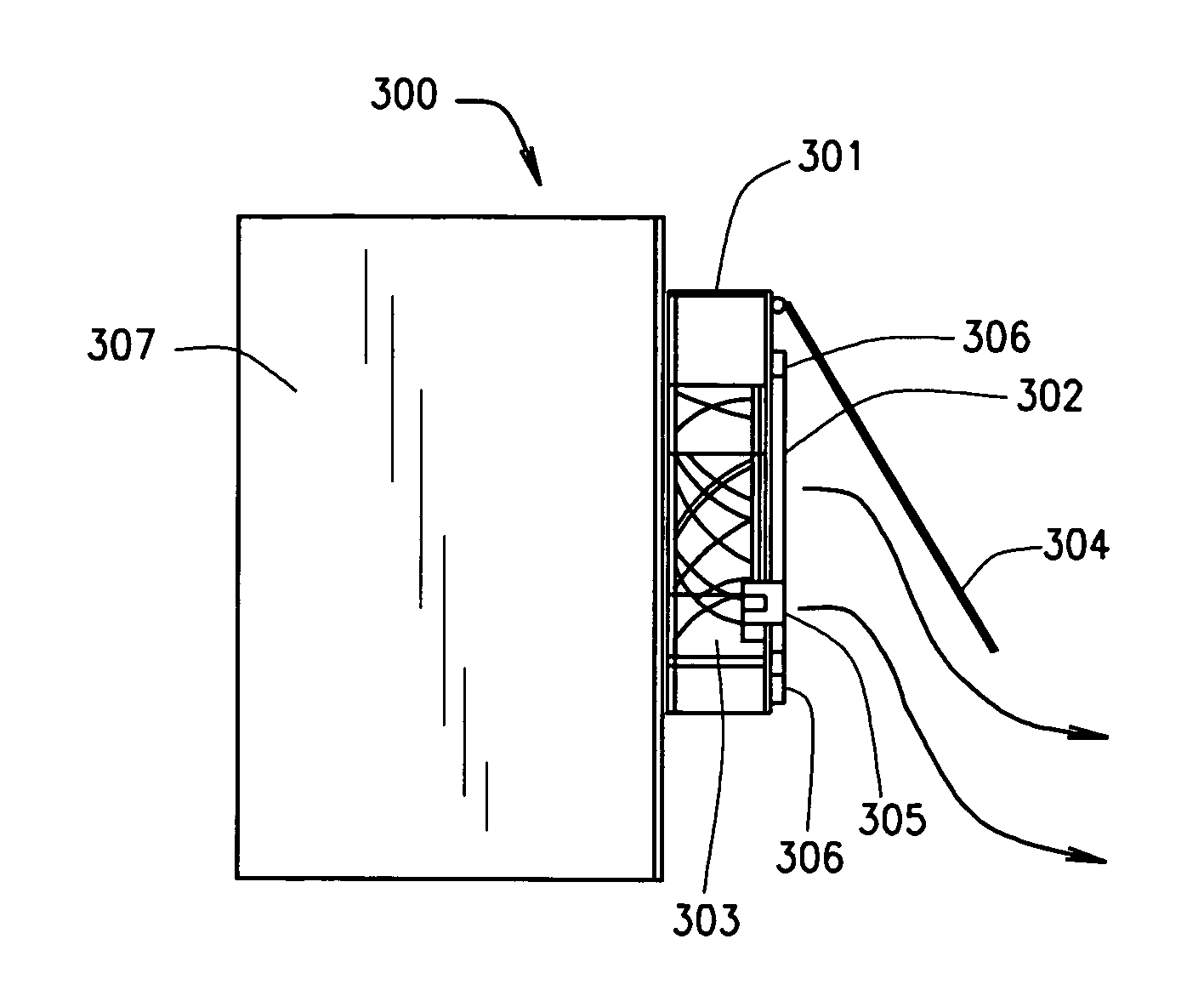
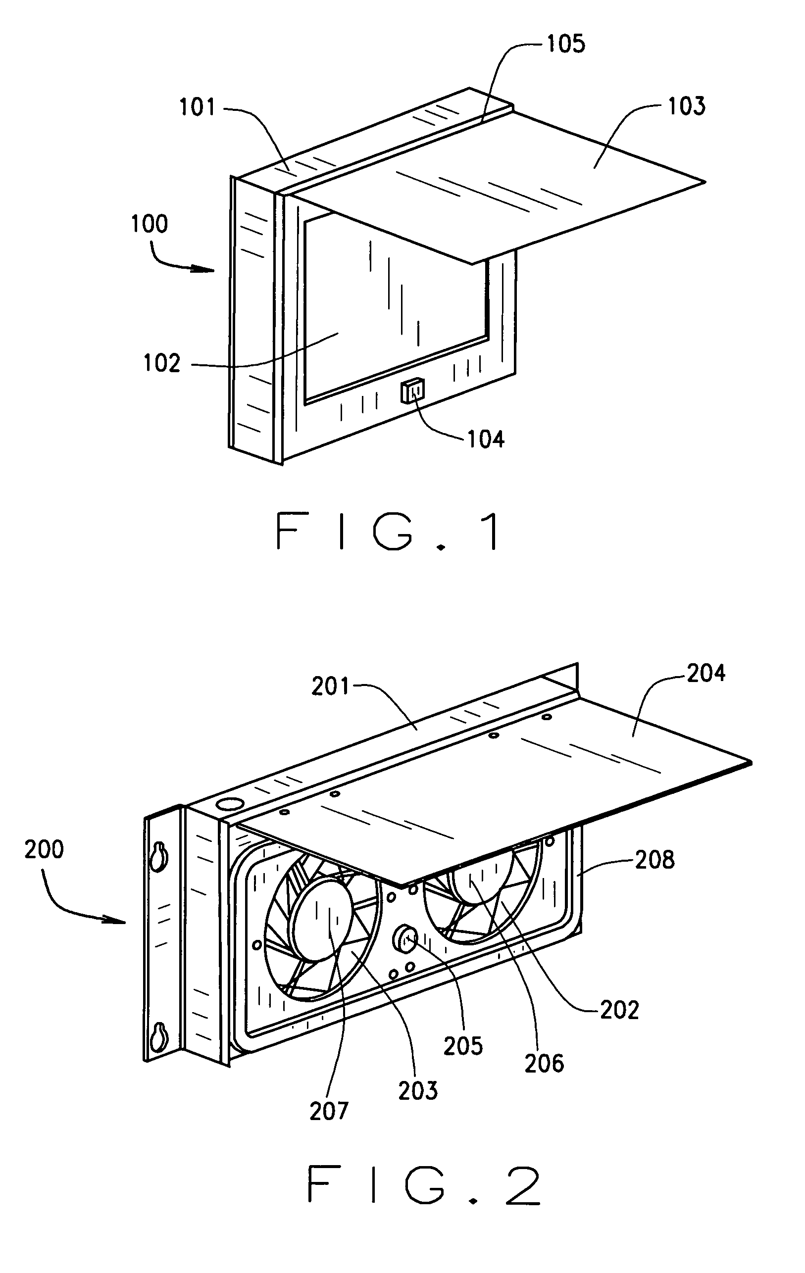
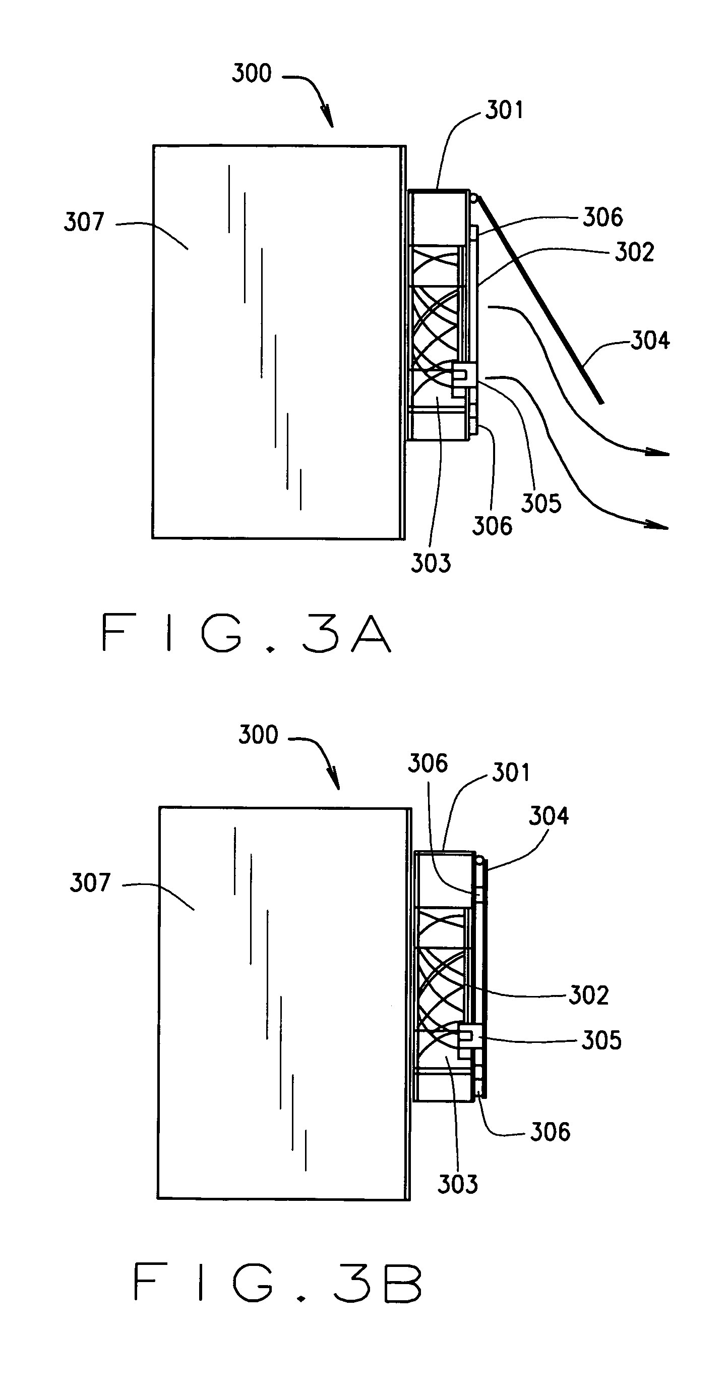
[0016]A ventilation assembly for an electronic equipment enclosure according to a first exemplary embodiment of the present invention is illustrated in FIG. 1 and indicated generally by reference numeral 100. As shown in FIG. 1, the ventilation assembly 100 includes a housing 101, a ventilation port 102, and a cover 103. The cover is movable between an open position (illustrated generally in FIG. 1) and a closed position. When the cover is in the closed position, the cover is positioned over the ventilation port 102. The ventilation assembly further includes an electromagnet 104 for selectively securing the cover 103 in its closed position.

[0017]In the embodiment of FIG. 1, the electromagnet 104 is mounted on a lower center portion of the housing 101. It should be understood, however, that the electrom...


PUM


Abstract

A ventilation assembly for an electronic equipment enclosure. The ventilation assembly includes a housing having at least one ventilation port, and a cover movable between an open position and a closed position. The cover is positioned over the ventilation port when the cover is in the closed position. The ventilation assembly further includes at least one electromagnet for selectively securing the cover in the closed position.

Description

CROSS-REFERENCE TO RELATED APPLICATION[0001]This application claims the benefit of U.S. Provisional Application No. 60 / 692,348 filed on Jun. 20, 2005. The disclosure of the above application is incorporated herein by reference.FIELD OF THE INVENTION[0002]The present invention relates to a ventilation assembly for an electronic equipment enclosure.BACKGROUND OF THE INVENTION[0003]A variety of electronic equipment enclosures (also referred to as cabinets) are available for housing various types of electronic equipment including, for example, telecommunications equipment. Many of these enclosures are provided with one or more exhaust vents for exhausting hot air from within the enclosure using fans or others means. These exhaust vents are commonly provided with electro-mechanical or pneumatic actuators for opening the exhaust vents when necessary to exhaust hot air from within the enclosure, and for closing the exhaust vents to protect the electronic equipment within the enclosure from...

Claims


Application Information

Patent Timeline
Patent Type & Authority Patents(United States)
IPC IPC(8): H05K7/20
CPCH05K7/20172
Inventor ELKINS, JIN
Owner VERTIV CORP
Why Eureka
Try Eureka