
Image forming apparatus
a technology of image forming and forming tubes, which is applied in the direction of electrographic process apparatus, instruments, optics, etc., can solve the problems of shortened service life of photosensitive drums, deterioration of photosensitive drum functions, and difficult removal
- Summary
- Abstract
- Description
- Claims
- Application Information
AI Technical Summary
Benefits of technology
Problems solved by technology
Method used
Image

Examples
first embodiment
[0057]First, a description will be given of the present invention.
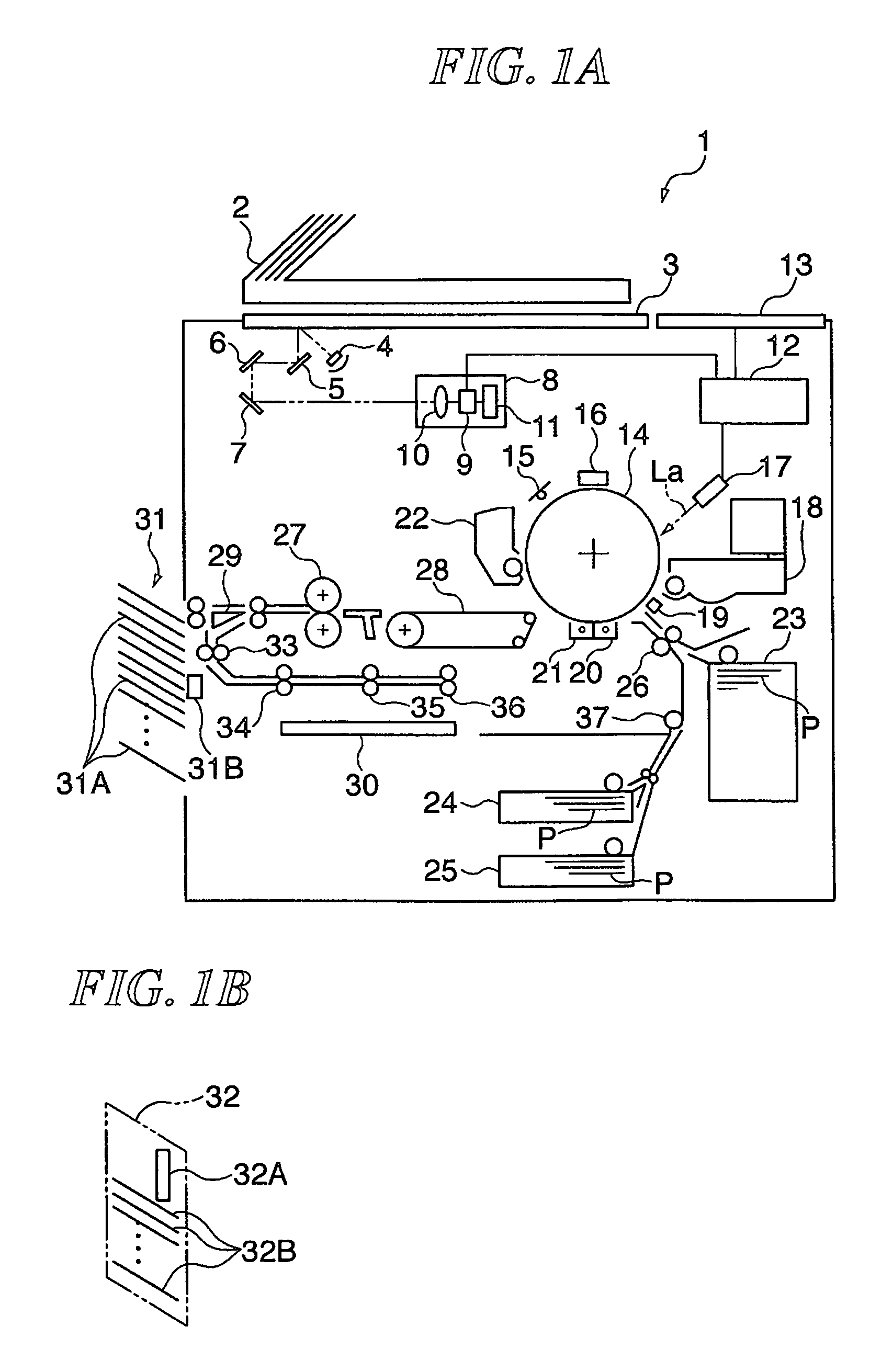
[0058]FIG. 1A is a view schematically showing the construction of an image forming apparatus according to the first embodiment of the present invention provided with a staple sorter. FIG. 1B is a view schematically showing the construction of the image forming apparatus according to the first embodiment of the present invention provided with a bookbinding machine.
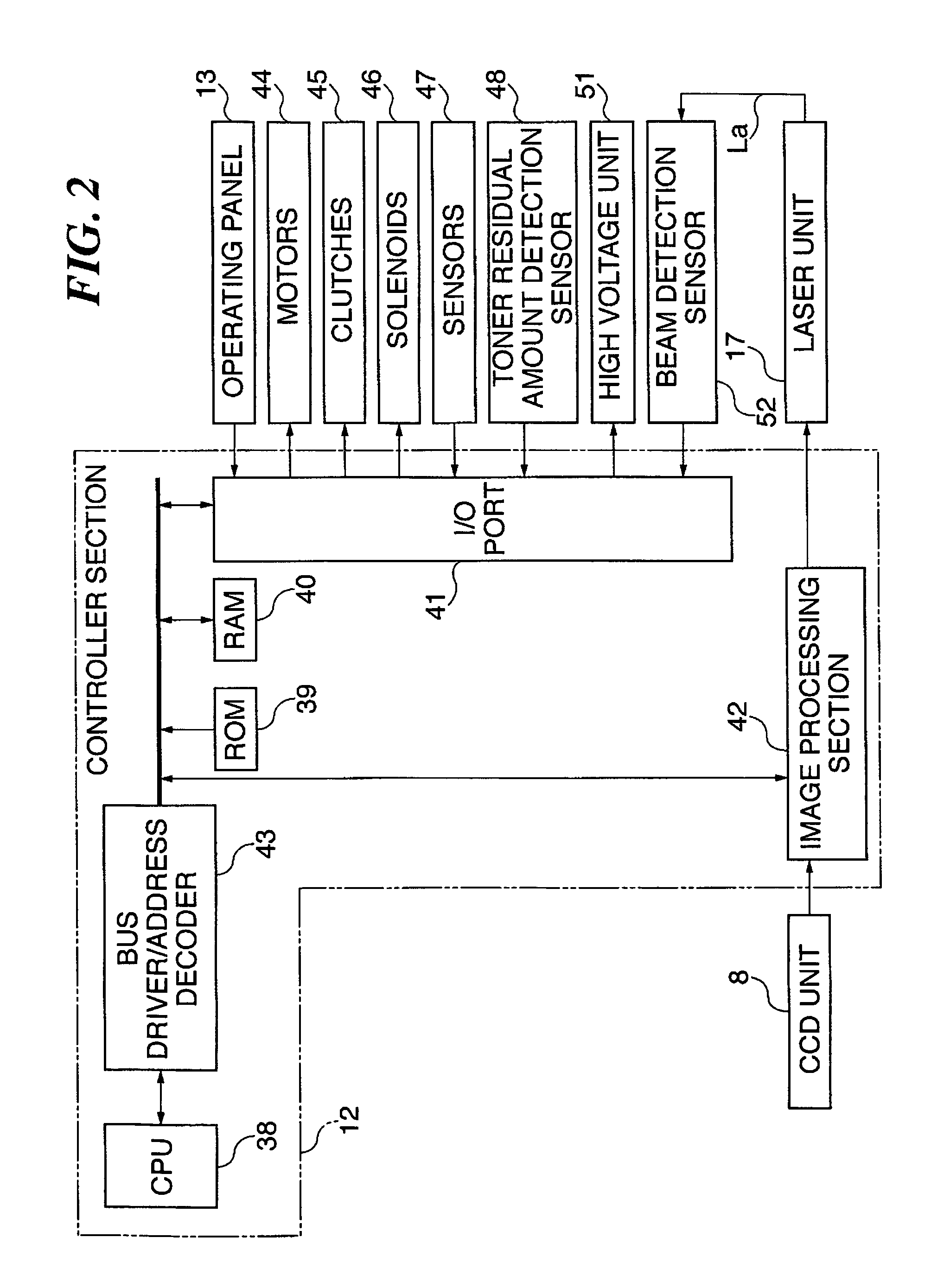
[0059]In FIG. 1, an image forming apparatus (copier) 1 has an automatic original feeding device 2, a CCD unit 8, a controller section 12, a photosensitive drum 14, a primary charger 16, a laser unit 17, a developing device 18, a transfer precharger 19, a transfer charger 20, a separating charger 21, a fixing unit 27, a staple sorter 31 (or a bookbinding machine 32), for example.
[0060]The automatic original feeding device 2 sequentially feeds originals to be read (not shown) to a predetermined position on an original platen glass 3 and ejects the originals hav...
second embodiment
[0125]Next, a description will be given of the present invention.
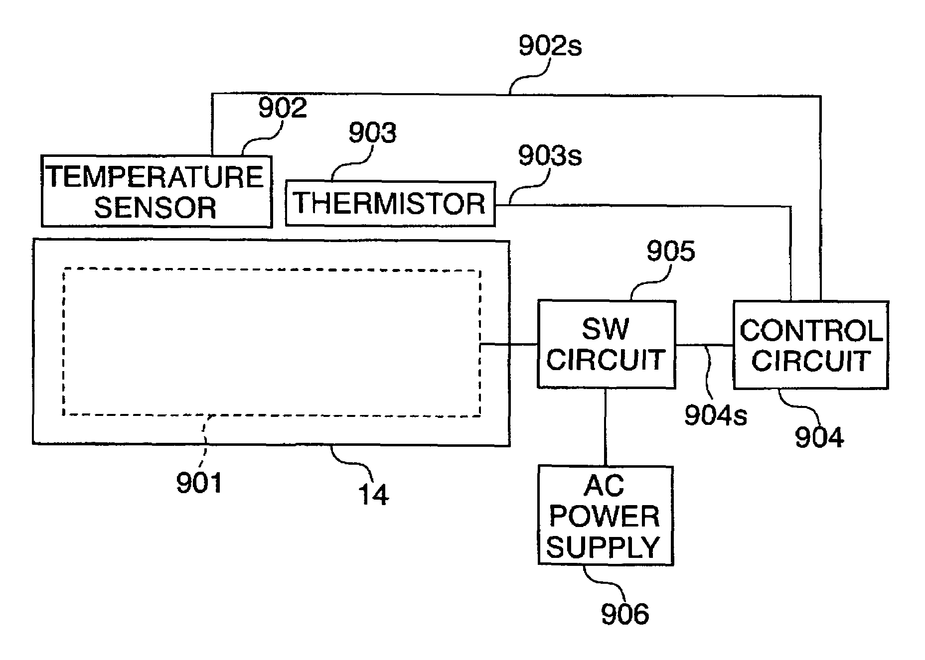
[0126]The second embodiment of the present invention differs from the first embodiment described above in that a non-contact thermistor 903 is not used as a limiter but used for correction of the temperature detected by a thermopile temperature sensor 902 and that a control circuit 904 has an arrangement shown in FIG. 10. The remaining components according to this embodiment are the same as the corresponding components according to the first embodiment described above (FIGS. 1 to 6), and hence descriptions thereof will be omitted.
[0127]Now, an arrangement of the control circuit 904 of the photosensitive drum temperature control system according to this embodiment will be described with reference to FIG. 10.
[0128]FIG. 10 is a block diagram showing an arrangement of the control circuit of the photosensitive drum temperature control system of the image forming apparatus according to the second embodiment of the present in...
PUM
 Abstract
Description
Claims
Application Information