Apparatus and method for separating transmit and receive signals for time division duplexing radio system

a radio system and transmit-received technology, applied in the field of apparatus and method for separating transmitted and received signals, can solve the problems of reducing the reliability of the radio system and the performance of the semiconductor, and achieve the effect of reducing the loss of signal transmission and reducing the leakage of transmit signals

Inactive Publication Date: 2008-03-25
ELECTRONICS & TELECOMM RES INST +4
View PDF9 Cites 4 Cited by
  • Summary
  • Abstract
  • Description
  • Claims
  • Application Information

AI Technical Summary

Benefits of technology

[0015]It is an advantage of the present invention to provide an apparatus for separating transmit and receive signals in a radio system for transmitting and receiving a signal by using a single frequency and antenna according to the present invention.
[0016]The present invention discloses an apparatus for separating transmit and receive signals in a radio system. The apparatus includes: a power amplifier for amplifying a transmit signal and outputting the signal; a transmitter circulator for passing the amplified transmit signal through a transmission path in which a signal loss is minimized, and respectively outputting a transmit leakage signal through first, second, and third leakage paths for reducing the transmit leakage signal leaked when the amplified transmit signal is passed; an antenna circulator for passing the transmit signal received through the transmission path and radiating the signal through an antenna, and outputting the leaked transmit leakage signal to the first leakage path to be reduced; and a receiver circulator for inverting the transmit leakage signals received through the first and third leakage paths with respect to each other and canceling the signals, and reducing the transmit leakage signal received through the second leakage path and outputting the signal.
[0017]The apparatus further includes a bidirectional combiner for sampling part of the transmit signal received through the transmission path of the antenna circulator and the receive signal externally received through the antenna; and a reflection coefficient measuring unit for measuring a reflection coefficient of the antenna by measuring power of the sampled transmit and receive signals, and interrupting transmit signal output of the power amplifier when the measured reflection coefficient exceeds a reference value.
[0018]The present invention also discloses a method for separating transmit and receive signals in a radio system. In the method, a) a transmit signal is amplified and the amplified signal is output, b) a transmit leakage signal is respectively output through first, second, and third leakage paths for reducing the transmit leakage signal leaked when the amplified transmit signal passes through a transmission path, c) the amplitude of the transmit leakage signal leaked when the transmit signal is radiated through the antenna is reduced by outputting the signal through the first leakage path, d) the transmit leakage signals received through the first and third leakage paths are canceled by each other, and the transmit leakage signal received through the second leakage path is reduced and the signal is output, and e) the receive signal externally received through the antenna is amplified and the signal is output.

Problems solved by technology

The high output switch is formed by using a semiconductor as a diode, and the semiconductor causes reduction of reliability of the radio system because the performance of the semiconductor is reduced when the semiconductor is used for a long time.
An additional control signal for operating the high output switch is also required, and it is a problem that a transmit / receive control signal is externally applied to the configuration of the radio system.
However, a filter and an amplifier for eliminating the leaked signals are required in the method for protecting the receiver, and therefore an additional device is still required to protect the receiver.

Method used


Image

  • Apparatus and method for separating transmit and receive signals for time division duplexing radio system
  • Apparatus and method for separating transmit and receive signals for time division duplexing radio system
  • Apparatus and method for separating transmit and receive signals for time division duplexing radio system

Examples


Embodiment Construction

[0025]In the following detailed description, only the preferred embodiment of the invention has been shown and described, simply by way of illustration of the best mode contemplated by the inventor(s) of carrying out the invention. As will be realized, the invention is capable of modification in various obvious respects, all without departing from the invention. Accordingly, the drawings and description are to be regarded as illustrative in nature, and not restrictive. To clarify the present invention, parts which are not described in the specification are omitted, and parts for which similar descriptions are provided have the same reference numerals.

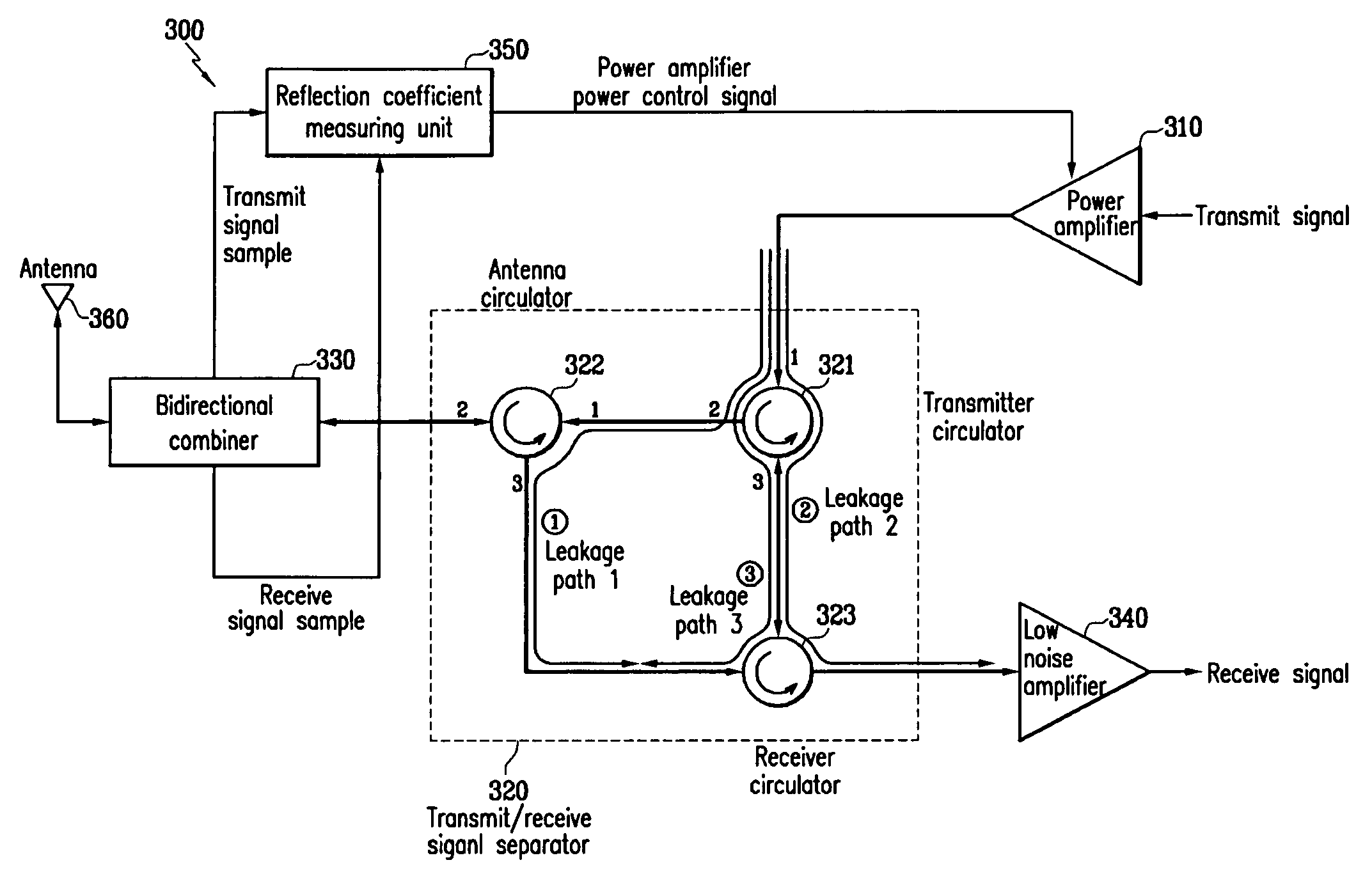
[0026]FIG. 3 shows a detailed diagram for representing an apparatus for separating transmit and receive signals in a radio system according to an exemplary embodiment of the present invention.

[0027]As shown in FIG. 3, the apparatus for separating transmit and receive signals in a radio system according to the exemplary embodiment of the...


PUM


Abstract

A receiver is protected by reducing a transmit leakage signal leaked when a transmit signal is radiated through the antenna by using three circulators (transmitter, antenna, and receiver). The transmitter and antenna circulators output the transmit leakage signal to be reduced to less than the transmit signal through a first leakage path. The transmitter and receiver circulators output the transmit leakage signal through a third leakage path and reduce the signal. The transmit leakage signals received through the first and third leakage paths are canceled, and that received through a second leakage path is output to a receiver. The transmit leakage signal has a 40 dB signal reduction compared to the transmit signal, and is transmitted to the receiver.

Description

CROSS REFERENCE TO RELATED APPLICATION[0001]This application claims priority to and the benefit of Korea Patent Application No. 2004-65075 filed on Aug. 18, 2004 in the Korean Intellectual Property Office, the entire content of which is incorporated herein by reference.BACKGROUND OF THE INVENTION[0002](a) Field of the Invention[0003]The present invention relates to a time division duplexing radio system. More specifically, the present invention relates to an apparatus and method for separating transmitted and received signals.[0004](b) Description of the Related Art[0005]Time division duplexing TDD is a technique used to transmit and receive on a single frequency by dividing one frame into a frame for transmitting and a frame for receiving. While different frequencies are used for transmitting and receiving in a conventional radio communication, the same frequency is divided into different time slots for transmitting and for receiving in time division duplexing, and therefore bidire...

Claims


Application Information

Patent Timeline
Patent Type & Authority Patents(United States)
IPC IPC(8): H04B1/46
CPCH04B1/525H04B1/44
Inventor JUNG, JAE-HOKIM, JOON-HYUNGLEE, KWANG-CHUN
Owner ELECTRONICS & TELECOMM RES INST
Why Eureka
Try Eureka