Power dividing and/or power-combining circuits with isolation

a power combining circuit and power division technology, applied in the field of electromechanical circuits, can solve the problems of reducing not adding constructive signals from the amplifier, so as to reduce the overall power input of the power amplifier, eliminate or minimize the effect of signal loss

Active Publication Date: 2016-06-07
ARMY US SEC THE THE
View PDF3 Cites 3 Cited by
  • Summary
  • Abstract
  • Description
  • Claims
  • Application Information

AI Technical Summary

Benefits of technology

[0021]Since the reflected signals from the amplifiers at the input to the power amplifier circuit are equal in amplitude, but angularly offset from each other by 120°, these three reflected vector signals, when combined, cancel and thus eliminate, or at least minimize, signal loss at the input to the power amplifier circuit.
[0022]For circuits containing four or more electronic devices, the actual selection of the delay component will differ in order to produce a reflected signal at the input which vectorally cancels thus resulting in zero or at least low signal loss.

Problems solved by technology

Otherwise, the signals from the amplifiers do not add constructively and power is lost.
One inherent problem with power signal level amplification in microwave systems is that the power amplifiers located between the divider and the combiner each exhibits an input reflection coefficient so that a portion of the signal provided by the divider to the power amplifier is reflected back to the input of the power amplifier circuit.
This reflected signal effectively reduces the overall power input to the power amplifiers.
This, in turn, reduces the overall efficiency of the power amplifier.
These previously known balanced combiner microwave power amplifier circuits, however, have been limited to a two amplifier configuration between the divider and the combiner.
In many situations, however, a simple two amplifier circuit produces insufficient output power for the microwave system.
However, the addition of extra divider / combiner pairs, each having a pair of power amplifiers electrically connected there between, increases the overall size and bulk of the microwave power system.
In many situations, such as monolithic microwave / millimeter wave integrated circuits (MMICs), the cascading of multiple balanced pairs of amplifiers is simply impractical due to the limited space available on the MMIC substrate.

Method used


Image

  • Power dividing and/or power-combining circuits with isolation
  • Power dividing and/or power-combining circuits with isolation
  • Power dividing and/or power-combining circuits with isolation

Examples


Embodiment Construction

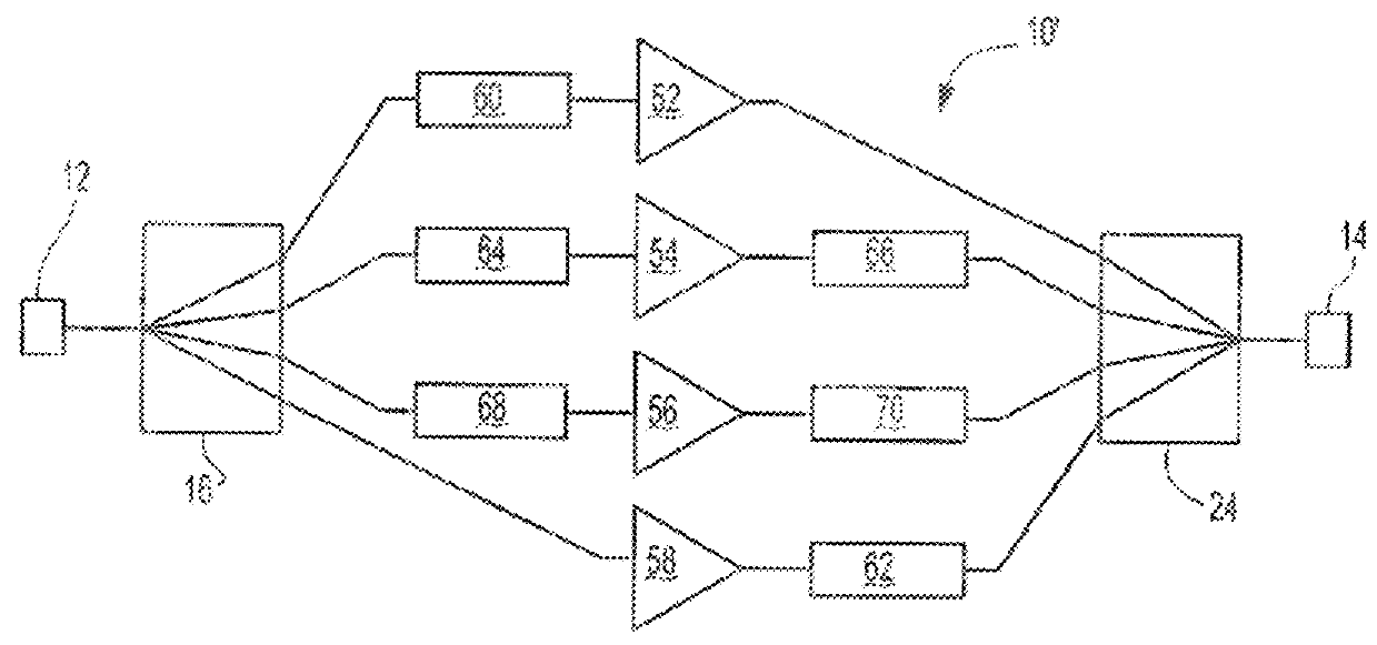
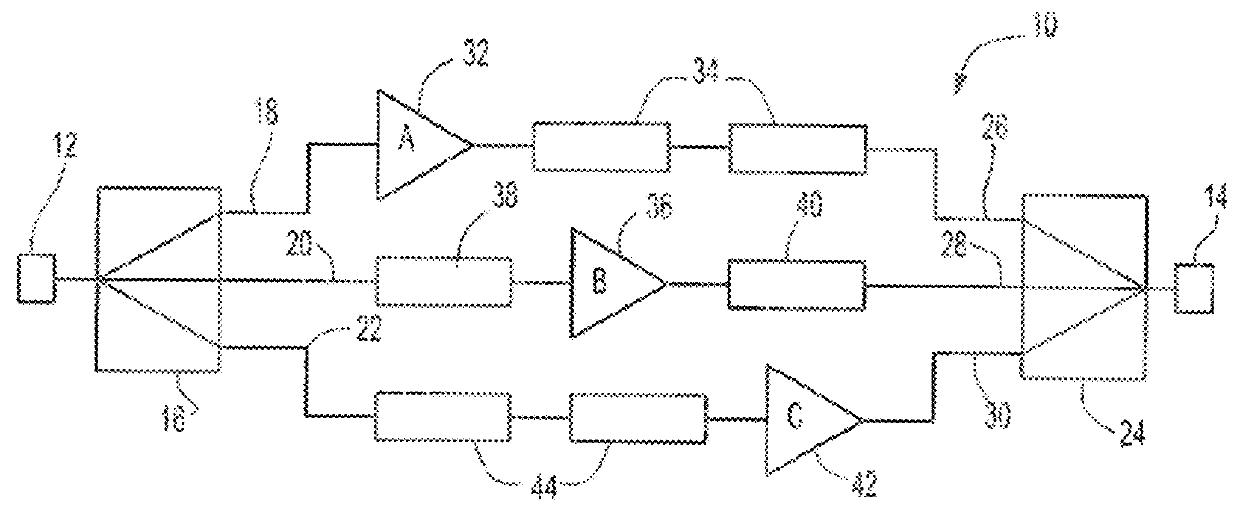
[0037]In general, the power-dividing and / or power-combining circuits described herein have inputs, outputs, at least three electrical pathways. At least one electronic device may be provided in each of the electrical pathways. Depending on the configuration of the inputs, outputs, the pathways and the electronic devices may be connected in parallel between the inputs and outputs. The electronic devices have substantially equal signal reflection at the inputs and / or the outputs. For example, the electronic devices may have input reflection coefficients and substantially equal output reflection coefficients. While the embodiments illustrated in the figures generally show a power amplifier as an electronic device, it should be appreciated that the circuits may include other electronic devices as well. For instance, the electronic devices may include amplifiers, switches, attenuators, mixers, filters, antenna elements (e.g., phased-array elements), etc. A power-dividing and / or power-com...


PUM


Abstract

Power-dividing and / or power-combining circuits have inputs, outputs, and at least three electrical pathways, with substantially equal input and output reflection coefficients. An electronic device may be provided in each of the pathways. Additionally, isolation circuits or devices can be inserted between signal lines to provide isolation between inputs, in the case of combining, or outputs, in the case of dividing. In one embodiment, multiple phase shift components are electrically connected to electronic devices in the electrical pathways. These phase shift components are selected so that a vector sum of the reflected signals from the inputs in combining and / or to the outputs in dividing is substantially minimized.

Description

CROSS REFERENCE TO RELATED APPLICATION(S)[0001]The present application is a continuation-in-part (CIP) application of U.S. patent application Ser. No. 13 / 922,980 filed on Jun. 20, 2013, which claims the benefit of U.S. Provisional Patent Application No. 61 / 835,688 filed on Jun. 17, 2013, both applications herein incorporated by reference in their entirety for all purposes.GOVERNMENT INTEREST[0002]The invention described herein may be manufactured, used, and licensed by or for the United States Government without the payment of royalties thereon.BACKGROUND OF THE INVENTION[0003]I. Field of the Invention[0004]The present invention relates generally to electronic circuits and, more particularly, to power-dividing and / or power-combining circuits.[0005]II. Description of Related Art[0006]Millimeter wave communication, radar, electronic warfare systems, also known as microwave systems, conventionally use amplifiers to increase the power output signal level. An increase in the output power...

Claims


Application Information

Patent Timeline
Patent Type & Authority Patents(United States)
IPC IPC(8): H01P5/12H01P9/00H03H7/18H03F3/60H03F3/189H03F3/21H01P1/18H03F3/68H03H7/42
CPCH01P1/182H01P1/184H01P9/00H03F3/189H03F3/211H03F3/602H03F3/68H03H7/185H03H7/422
Inventor DARWISH, ALI M.HUNG, HINGLOI ALFRED
Owner ARMY US SEC THE THE
Why Eureka
Try Eureka