Among these, the combination of print quality and speed is often considered most challenging.
However, the amount of heat irradiated from gas
discharge lamps is usually very high, which places constraints on
system design.
Overheating may cause operational and maintenance problems.
Excessive heat also limits the ability of inkjet printers to print on some
heat sensitive substrates.
However, if the lamp power is lowered to avoid deleterious heating effects, there may be a
trade off, e.g. in lower print quality and speed, or curing may not be achieved at all.
However even with the highest power UV LED chips available to date, inkjet printers that solely use UV LEDs for curing still have some problems such as low print quality and / or speed.
Under some standard print quality examination tests, print samples produced by UV LED inkjet printers may show evidence of improper cure with surface curing problems, adhesion problem, or
color bleeding problems.
These arrangements may have difficulty in achieving an intensity that is high enough for good print quality for some applications.
More densely packed LED chips may be provided to achieve
high intensity; however liquid cooling may then be required which adds to
system complexity and cost.
Such UV LED heads are very expensive because of the density and large number of LED chips required.
This type of focused beam may be overkill, i.e. delivering a
high intensity over a short period of time may result in low curing efficiency.
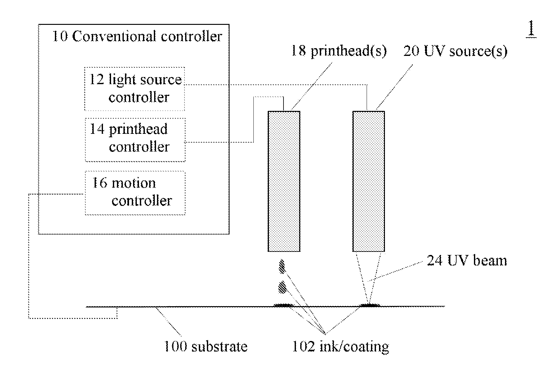
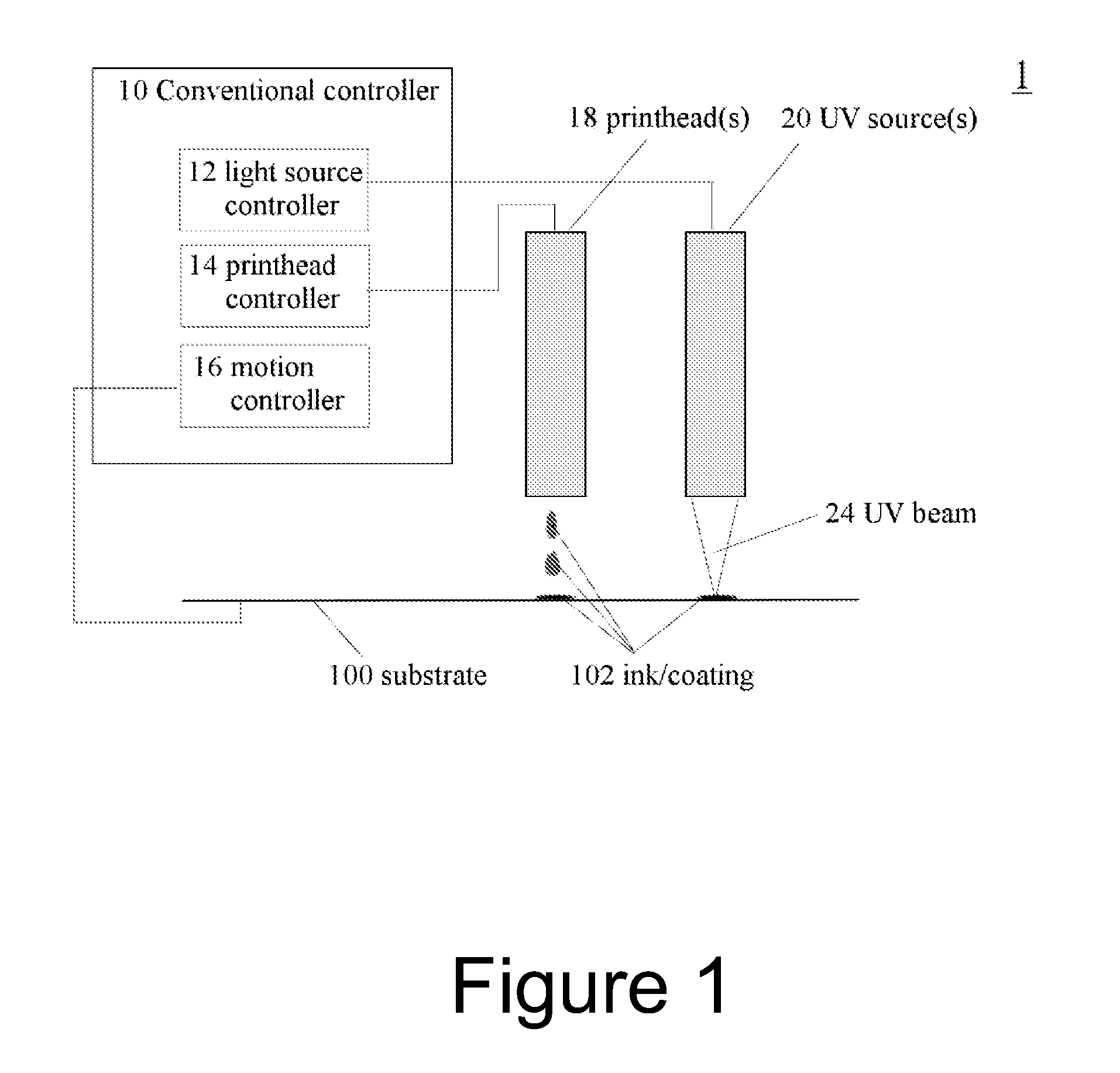
For example, for scanning type inkjet printers with
continuous irradiation, although the ink
layers may receive multiple UV illuminations (i.e. multiple scans), the period between each illumination is determined e.g. by the configuration of the print engine and one or more light sources, and scanning rate, for the print process and usually does not provide the flexibility of adjustment to match the optimal UV irradiation requirements by the ink
chemistry.
The period between each two illuminations may not effectively match the
dark reaction requirements of the ink
chemistry.
In systems providing a focused
single beam, such UV sources also do not take
advantage of dark reactions effectively.
These systems do not provide sufficient control of periods of irradiation vs. dark polymerization for optimizing or improving the cure efficiency.
However, for some applications this solution may not be suitable, or too complex, and alternative or simpler, lower cost solutions may be required.
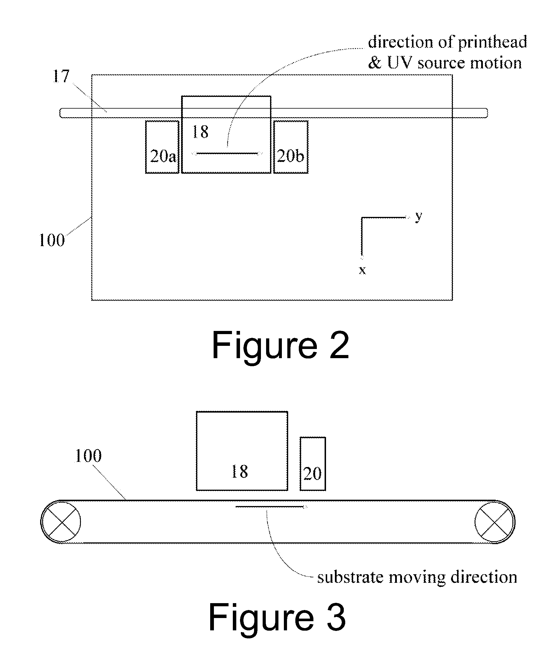
Also even if the intensity and beam profile of a light source may be adjusted, it does not overcome the
disadvantage mentioned above that in scanning type inkjet printers, the period between scans is fixed and dependent on the apparatus and cannot provide control over an interval of dark polymerization between periods of irradiation.
Thus known
UV curing systems such as inkjet printers, and particularly scanning type inkjet printers, may not provide sufficient control of the spatial pattern of irradiation, and dark intervals, leading to problems with print quality or curing efficiency for some applications.

