Indeed, that technical hurdle is well known and attributable to a
single component, namely to the BEV's battery.
Another serious drawback of batteries is that they lose a very substantial portion (about 50%) of their charge holding capacity as they age, which reduces the
driving range by the same percentage.
Tesla's quick changing battery stations will not provide the answers to the needs of the
mass market either.
Purchasers of the Nissan Leaf® vehicles have to contend with recharging their BEV batteries every 80 miles or so, which requires going out of one's way to find a
charging station and losing close to an hour, which is unacceptable.
The government's cash incentive credits, currently about $7,500 per vehicle, to spur BEV purchases, are doomed to failure, because they do not address the real drawbacks that prevent adoption of electrical vehicles on a wide scale.
Also, the buyer is essentially “stuck” with the same physical battery for its entire life, which is problematic because technology improves all the time, and newer batteries come online that have greater energy densities, lower costs, etc.
Yet, the original purchaser would have to lose the entire value of the battery included in the vehicle purchase price if they chose to discard the original battery prematurely.
And the
end user is limited to the
driving range of a single battery, with no ability, similar to the IC vehicle driver, to buy and purchase
gasoline fuel literally anywhere at the hundreds of thousands of
gasoline stations located everywhere.
Another
disadvantage is that single-vehicle families cannot purchase the BEV, even if a vehicle having a 100
mile range is sufficient for their typical needs.
Lithium cobalt oxide (LiCoO2) batteries offer
high energy density and are used only in hand-held electronic devices because they present safety risks when damaged in an automobile
crash.
But, as noted above, the battery power that can be located in the space that is currently occupied by a
gasoline tank will only produce about 80 miles of driving with a battery price tag on the order of $20,000, which is entirely unacceptable.
Hence, to drive 320 miles, a battery would weigh about 2,200 pounds, which is basically impossible for a
mass market automobile.
Thus, if the battery is kept at over 100° F., about 15% per month of the
battery charge is passively lost.
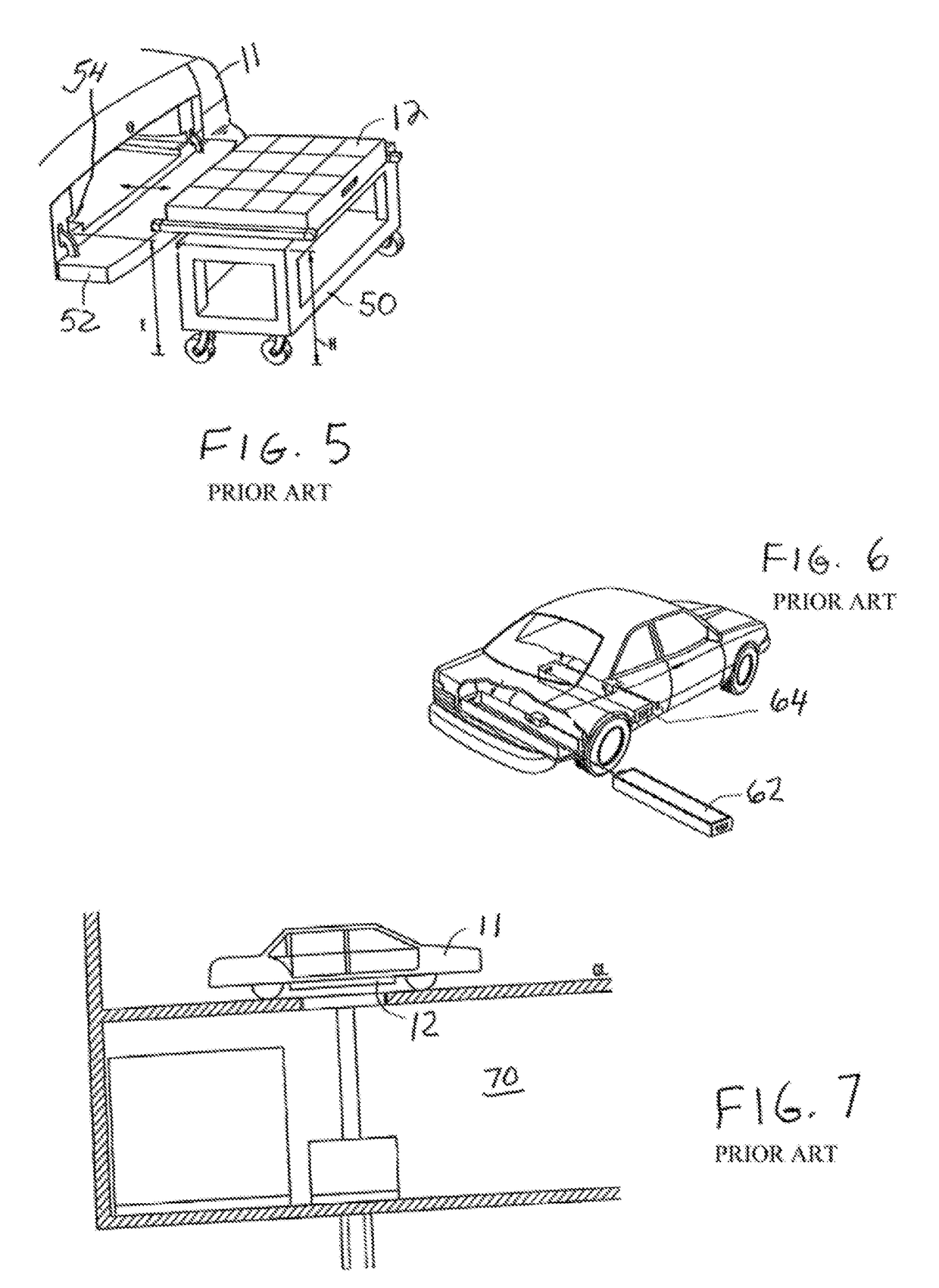
But the Better Place and Tesla exchange stations require investment of millions of dollars to
handle batteries that weigh hundreds of pounds.
A BEV owner or driver could never
handle a battery that weighs 500 or 600 pounds in this manner.
Besides, the exposed electrodes have a
voltage potential of approximately 100 volts DC, which should not be handled at the private level.
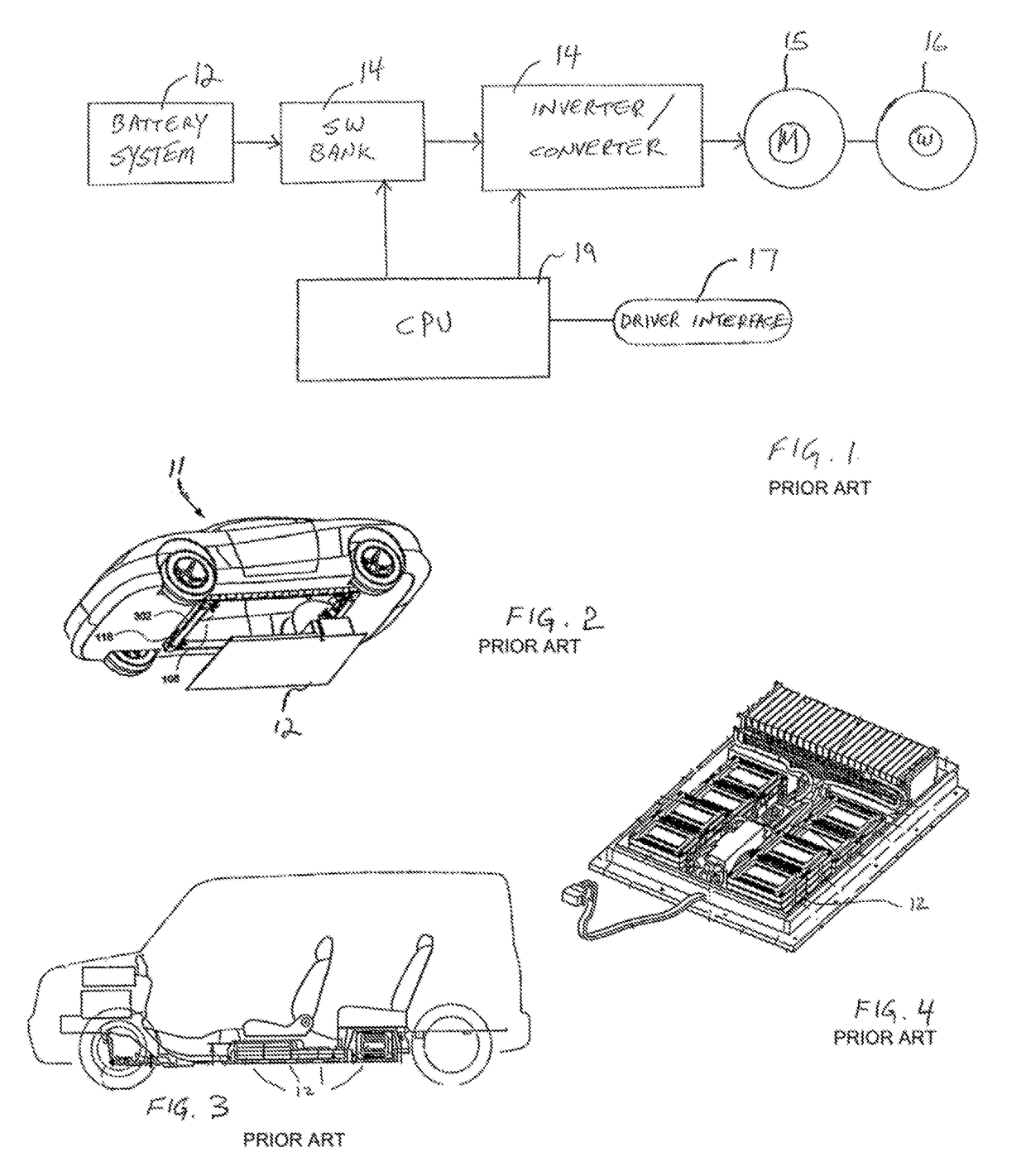
But still, each battery module can power the vehicle, requiring that it weigh hundreds of pounds.
Another battery can be loaded by inserting it laterally through an opening at one of the
doors of the vehicle, which interferes with the desire to keep the car aesthetics intact.
It is a very complicated arrangement of various battery modules located at the bottom of the vehicle.
All of these battery exchange systems are very expensive, requiring millions of dollars in infrastructure initial costs.
At page 21, the report asserts that BEVs, under current battery technology, are actually more expensive to operate over their fifteen year life cycle than CVs and Hybrids.

