Dry 3-way catalytic reduction of gas turbine NOx

a gas turbine and catalytic reduction technology, which is applied in the direction of machines/engines, electric generator control, separation processes, etc., can solve the problems of process suffering from known deficiencies, adversely affecting the cost and durability of construction materials, and increasing public scrutiny, so as to reduce the amount of nox in the exhaust gas, reduce the amount of oxygen remaining, and increase the co2 concentration

Active Publication Date: 2009-11-19
GENERAL ELECTRIC CO
View PDF13 Cites 301 Cited by
  • Summary
  • Abstract
  • Description
  • Claims
  • Application Information

AI Technical Summary

Benefits of technology

[0017]It has now been found that a number of significant benefits can be achieved using EGR under the process conditions described below. In particular, a reduction in the amount of NOx in the exhaust gas can be achieved at higher levels of EGR, while at the same time increasing the CO2 concentration and significantly reducing the amount of oxygen remaining in the exhaust gas stream, i.e., to levels at or below 4%. Even more significant, under the EGR conditions described below, it has been discovered that the exhaust gas stream can be treated in a much more economical and efficient manner, namely by using a dry 3-way ca

Problems solved by technology

The combustion normally takes place under relatively “lean” conditions, i.e., more than the stoichometric amount of oxygen necessary for complete combustion of the hydrocarbon fuel components in order to maintain the combustion temperature below certain practical limits (which, if too high, would adversely affect the cost and durability of materials of construction).
One significant deficiency of open Brayton cycle and combined cycle gas turbine systems is that the exhaust gas includes various oxides of nitrogen (NOx) and a significant amount of carbon dioxide (CO2) and carbon monoxide (CO), all of which are now under increasing public scrutiny for possible adverse environmental effects.
However, such processes suffer from known deficiencies, including the possible formation of other nitrogen-based compounds that require further treatment before being released into the atmosphere.
However, such operations tend to decrease the overall efficiency of the gas turbine and fail to initially remove sufficient amounts of NOx from the exhaust str

Method used


Image

  • Dry 3-way catalytic reduction of gas turbine NOx
  • Dry 3-way catalytic reduction of gas turbine NOx
  • Dry 3-way catalytic reduction of gas turbine NOx

Examples


Embodiment Construction

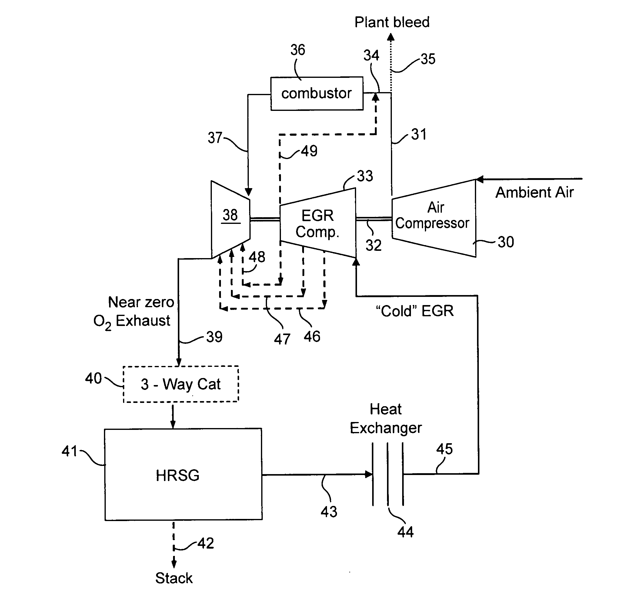
[0028]An exemplary embodiment of the power generation system according to the invention includes the following basic components: A gas compressor that increases the pressure of ambient air fed to the system; a combustor capable of combusting a mixture of fuel (such as a hydrocarbon or syngas) and compressed ambient air to generate a high temperature exhaust gas stream; a conventional gas turbine engine downstream of the combustor with turbine blades moveable by the force of the expanded, high temperature exhaust gas; a high percentage EGR stream fed to the combustor; a 3-way catalytic reactor downstream of the gas turbine engine that contacts an exhaust gas stream having less than 4% by volume oxygen and removes a substantial amount of the NOx components (typically about 70%); a heat recovery steam generator (HRSG); a cooler (heat exchanger) to lower the temperature of a portion of the exhaust gas leaving the HRSG to form a cooled EGR stream; an EGR compressor that increases the pre...


PUM

PropertyMeasurementUnit
Percent by volumeaaaaaaaaaa
Temperatureaaaaaaaaaa

Abstract

A power generation system capable of eliminating NO, components in the exhaust gas by using a 3-way catalyst, comprising a gas compressor to increase the pressure of ambient air fed to the system; a combustor capable of oxidizing a mixture of fuel and compressed air to generate an expanded, high temperature exhaust gas; a gas turbine engine that uses the force of the high temperature gas; an exhaust gas recycle (EGR) stream back to the combustor; a 3-way catalytic reactor downstream of the gas turbine engine outlet which treats the exhaust gas stream to remove substantially all of the NOx components; a heat recovery steam generator (HRSG); an EGR compressor; and an electrical generator.

Description

[0001]This invention was made with Government support under Contract No. DE-FC26-05NT42643 awarded by the Department of Energy. The Government has certain rights in the invention.FIELD OF THE INVENTION[0002]This invention relates to the reduction and / or abatement of gas emissions from power generation plants, particularly nitrogen-oxide compounds present in the exhaust streams of plants that rely on a gas working fluid to generate electrical power. More particularly, the invention relates to a combined cycle gas turbine power generation system using a gaseous working fluid that has been compressed, combusted and expanded to drive a gas turbine engine, with at least a portion of the exhaust from the gas turbine being recycled to the combustor as an exhaust gas recirculation (“EGR”) stream. The invention also relates to a method for treating the exhaust gas using a 3-way catalyst to effectively eliminate selected pollutants (particularly NOx), without adversely effecting the amount of...

Claims


Application Information

Patent Timeline
IPC IPC(8): F01D15/10F02C7/14F02C7/08F02C1/00
CPCB01D53/8625B01D53/8643B01D2255/1021B01D2255/204B01D2255/206Y02T10/22B01D2255/2092F02C3/34F02C6/18Y02E20/16B01D2255/20715Y02T10/12
Inventor ANAND, ASHOK KUMARWEST, JAMES ANTHONYKRAEMER, GILBERT OTTOKARIM, HASAN ULDRAPER, SAM DAVIDBERRY, JONATHAN DWIGHT
Owner GENERAL ELECTRIC CO
Why Eureka
Try Eureka