Graphite electrode and manufacturing process thereof, and a carbon dioxide generator

a graphite electrode and carbon dioxide technology, applied in the direction of electrolysis process, electrolysis components, cells, etc., can solve the problem that the conventional carbon dioxide generator with graphite electrodes cannot produce carbon dioxide with sufficient concentration to effectively attract mosquitoes and insects, and achieves good energy saving, easy replacement, and stable quantity

Active Publication Date: 2019-05-30
NINGBO DAYANG TECH CO LTD
View PDF1 Cites 3 Cited by
  • Summary
  • Abstract
  • Description
  • Claims
  • Application Information

AI Technical Summary

Benefits of technology

[0019]In comparison with the prior art, when the graphite electrode of the present invention is used as the anode plate in the electrolytic cell of the carbon dioxide generator, the carbon dioxide in the gas produced by electrolysis could reach 10 v % or more, and

Problems solved by technology

As an attractant for mosquitoes and insects, conventional carbon dioxide generator with graphite electrode c

Method used


Image

  • Graphite electrode and manufacturing process thereof, and a carbon dioxide generator
  • Graphite electrode and manufacturing process thereof, and a carbon dioxide generator
  • Graphite electrode and manufacturing process thereof, and a carbon dioxide generator

Examples


embodiment 1

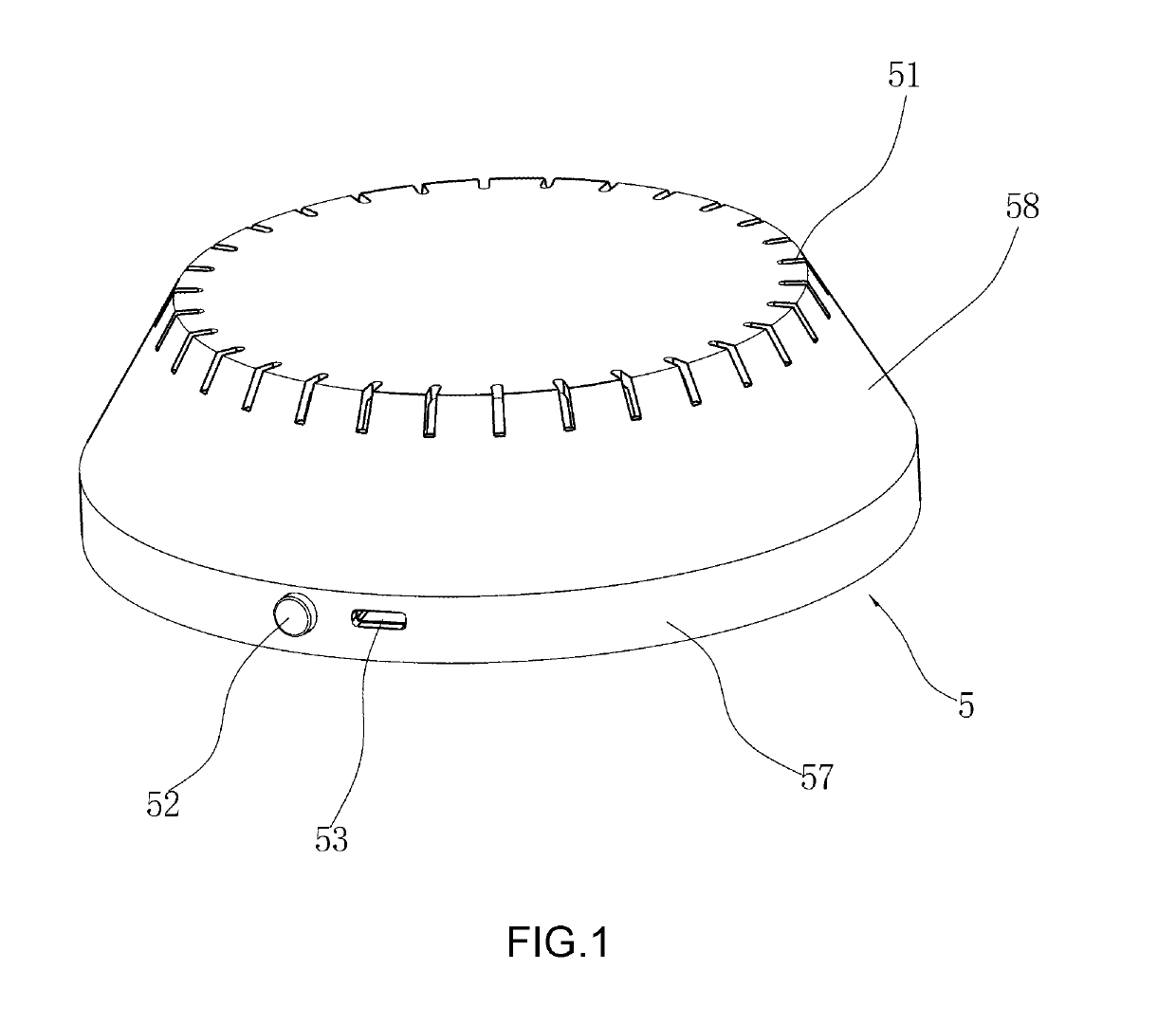
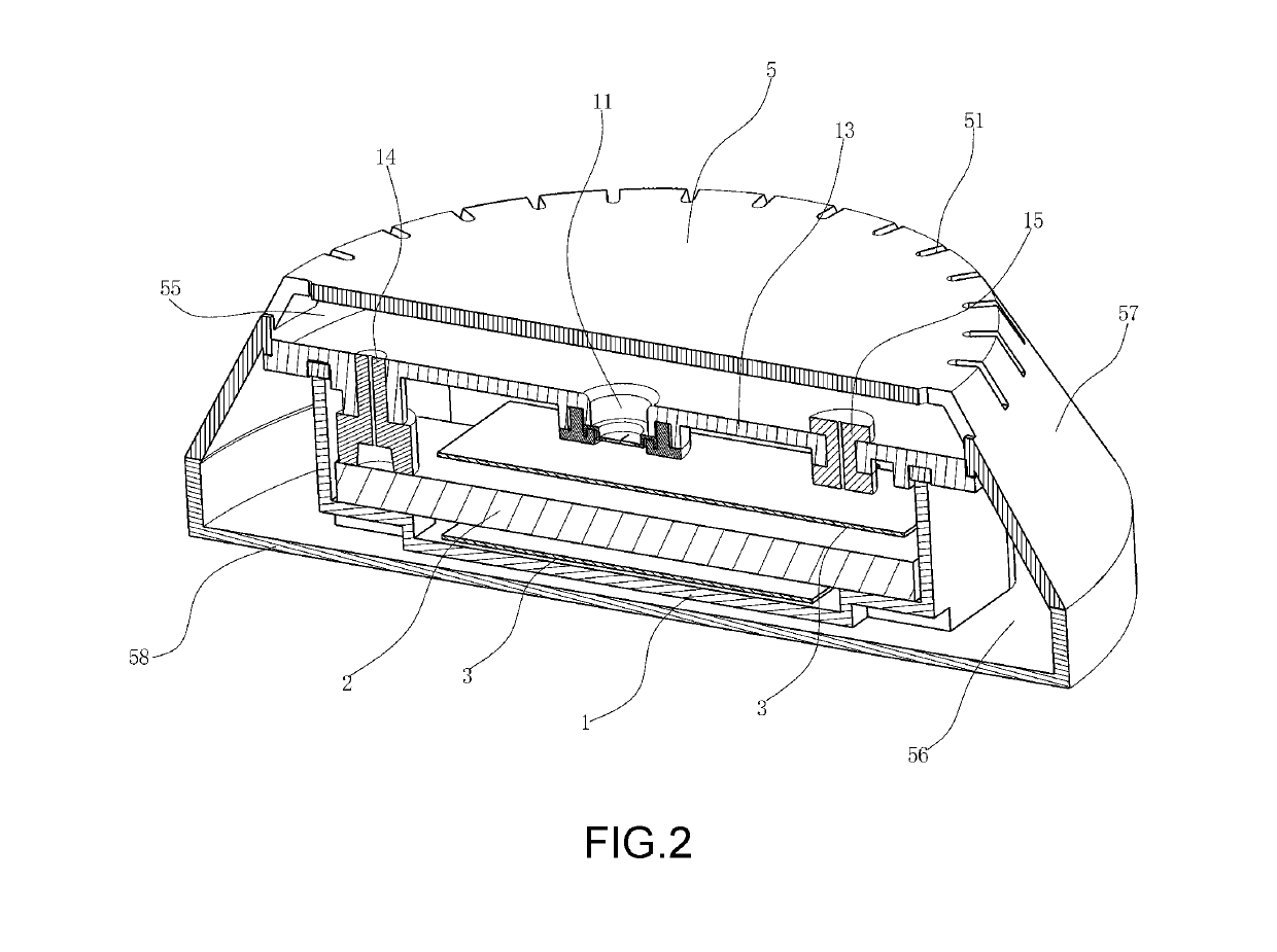
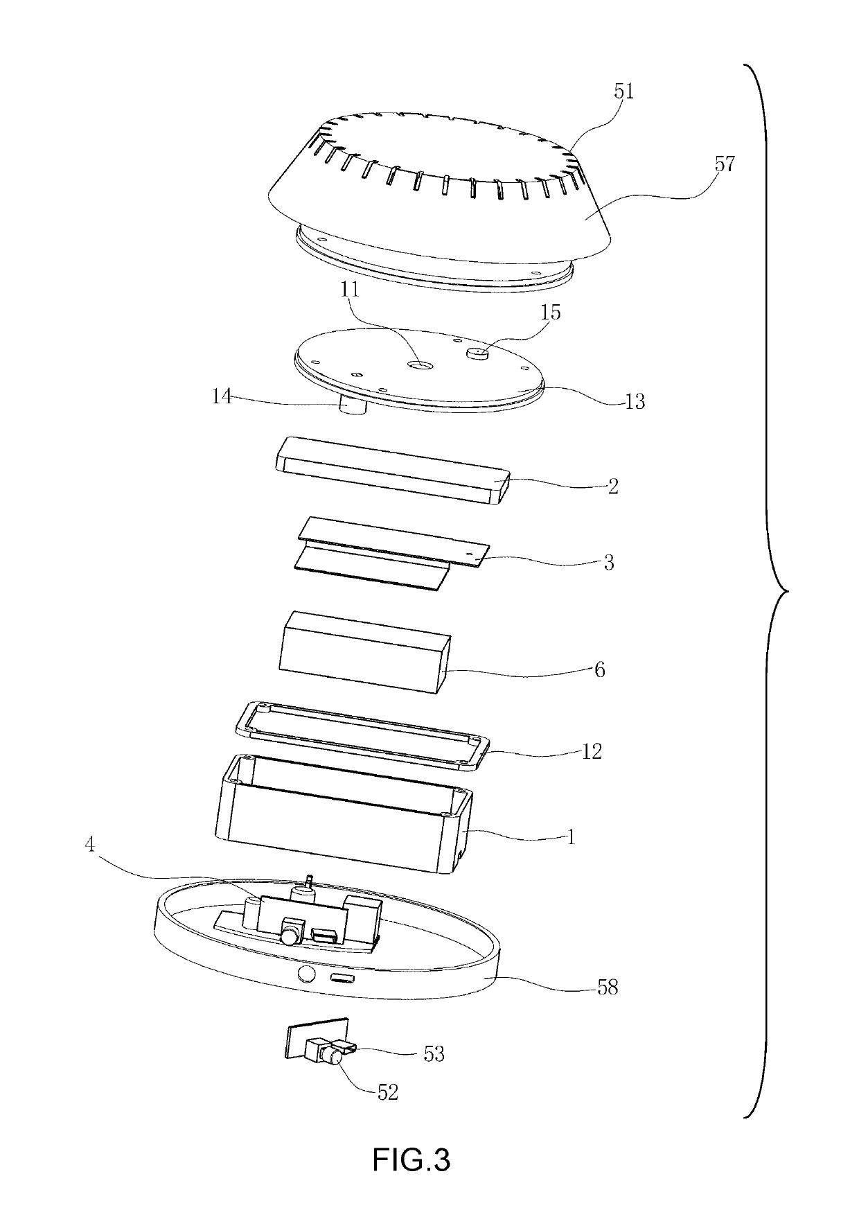
[0024]As illustrated in FIGS. 1 to 3, the carbon dioxide generator comprises:

[0025]a box body 1 for receiving an electrolyte solution, a graphite electrode 2 and a cathode plate 3. The box body 1 of the present embodiment is an open end container having an upper open end sealingly connected to a partition plate 13 via a sealing ring 12. The partition plate 13 divides an internal cavity of a casing 5 into a lower cavity 56 and an upper cavity 55 which are isolated from each other. A ventilation hole 11 which communicates with the box body 1, and a positive connection rod 14 and a negative connection rod 15 which connect to an electrolysis circuit 4 respectively are disposed on the partition plate. The positive connection rod 14 is electrically connected to the graphite electrode 2. The negative connection rod 15 is electrically connected to the cathode plate 3.

[0026]In the present embodiment, the cathode plate 3 has a U-shaped cross section and encompasses the graphite electrode 2.

[0...

embodiments 2 to 8

[0037]The carbon dioxide generator in Embodiments 2 to 8 has the same structure as the carbon dioxide generation in Embodiment 1, but the compositions of the electrolyte solution and the graphite electrode are different. Please refer to Table 1 for details. In Table 1, the remaining amount is the graphite amount, i.e. after adding the graphite amount the total would be 100%.

[0038]Control

[0039]The carbon dioxide generator used in the Control has the same structure as the carbon dioxide generator in Embodiment 1, but the graphite electrode used is a conventional graphite electrode in the prior art, and the electrolyte solution is water.

TABLE 1Hexamethyl-ElectrolyteCompositionAdhesiveenetetramineFirst additiveSecond additivesolutionEmbodiment 2thermoplastic1%polylactic acid,calcium1% sodiumphenolic resin8%carbonate, 5%bicarbonate2123, 12%carbonnanotubes,0.5%calciumstearate, 1%aluminiumoxide, 0.5%Embodiment 3bisphenol A2%glucose, 5%carbon black,3% sodiumepoxy resin,1%sulfate18%zinc oxid...


PUM


Abstract

The present invention relates to a graphite electrode and manufacturing process thereof, and a carbon dioxide generator, wherein the graphite electrode comprises the following in weight percentage: graphite powder 50%-90%; adhesive 10%-40%; first additive 1%-30%; second additive 0.1%-10%; wherein the adhesive comprises at least one of phenolic resin, bisphenol A epoxy resin and urea formaldehyde resin; the first additive is selected from at least one of the following: polylactic acid, carbonate, monosaccharide, oligosaccharide and polymethacrylates; the second additive is selected from at least one of the following: carbon black, carbon nanotubes, silicon carbide, boron nitride, silicon oxide, aluminium oxide, zinc oxide, iron oxide, titanium dioxide, calcium carbonate, stearic acid, zinc stearate and calcium stearate. The carbon dioxide concentration of the gas obtained by the electrolysis of the present invention reaches 10 v % or more, and the gas produced is stable in quantity.

Description

BACKGROUND OF THE INVENTION[0001]Graphite is used as electrode for producing carbon dioxide during electrolysis. The carbon dioxide in the electrolytic gas is within 1-2 v %, and the carbon dioxide concentration is very low. As an attractant for mosquitoes and insects, conventional carbon dioxide generator with graphite electrode could not produce carbon dioxide with sufficient concentration to effectively attract mosquitoes and insects.BRIEF SUMMARY OF THE INVENTION[0002]In view of the aforesaid disadvantages now present in the prior art, the present invention provides a graphite electrode which significantly increases carbon dioxide concentration in electrolytic gas under same electrolysis conditions.[0003]In view of the aforesaid disadvantages now present in the prior art, the present invention further provides a manufacturing process of graphite electrode which significantly increases carbon dioxide concentration in electrolytic gas under same electrolysis conditions.[0004]In vi...

Claims


Application Information

Patent Timeline
IPC IPC(8): C25B11/12C25B1/00C25B11/00C25B9/17
CPCC25B11/12C25B1/00C25B11/00C25B9/17C25B11/043
Inventor ZHENG, JUN
Owner NINGBO DAYANG TECH CO LTD
Why Eureka
Try Eureka