Ink jet printing apparatus and ink jet printing method

a printing apparatus and ink jet technology, applied in printing mechanisms, spacing mechanisms, printing, etc., can solve the problems of difficult to reduce the amount of ink ejection thereafter, hardly possible to suppress the increase in ink ejection, and the density of a printed image may become lower than intended

Inactive Publication Date: 2008-07-29
CANON KK
View PDF9 Cites 12 Cited by
  • Summary
  • Abstract
  • Description
  • Claims
  • Application Information

AI Technical Summary

Benefits of technology

[0013]An object of the present invention is to provide an ink jet printing apparatus and an ink jet printing method, which are capable of printing a high-definition image by stabilizing the amount of ink ejection through the selection of the driving condition with the temperature of the printing head being taken into consideration.
[0014]Another object of the present invention is to print a high-definition image by stabilizing the amount of ink ejection through the selection of the driving condition with the heat conductivity of the electrothermal converter being taken into consideration.
[0026]According to the present invention, it is possible to obtain a desired amount of ink ejection stably by changing the voltage of the drive pulse for an electrothermal converter. Specifically, when foaming the ink by use of the thermal energy generated by the electrothermal converter and ejecting the ink by use of the foaming energy, the amount of ink ejection depends on the size of that bubble. The size of the bubble is determined by the voltage and the pulse width of the drive pulse for the electrothermal converter, and the amount of ink ejection can be controlled by controlling both of these parameters.
[0028]The inventor of the present invention actually measured the size of bubbles to be formed on an electrothermal converter. It was confirmed that raising the voltage and reducing the pulse width of the drive pulse produced the bubbles apparently smaller. This measurement was carried out so as to keep the energy inputted to the electrothermal converter was constant. The voltage is determined in response to the pulse width so that the size of the pulse width might not cause fluctuation in the energy inputted to the electrothermal converter. In this way, by changing the voltage and the width of the drive pulse simultaneously, it is possible to control the foaming force of the ink jet printing head and also to change the amount of ink ejection when using the same electrothermal converter.
[0031]Moreover, the heat conductivity of the electrothermal converter may be rated as the heater rank corresponding to elapsed time from application of the drive pulse thereto to initiation of ink foaming. An electrothermal converter that has high heat conductivity with the above elapsed time being short, i.e. an electrothermal converter having a small energy threshold necessary for ink ejection, ranks low in the heater rank. In contrast, an electrothermal converter that has low heat conductivity with the above elapsed time being long, i.e. an electrothermal converter having a large energy threshold necessary for ink ejection, ranks high in the heater rank. Accordingly, it is possible to obtain a constant amount of ink ejection at all times by making the voltage of the drive pulse lower and the pulse width larger for a lower-rank heater, and by making the voltage of the drive pulse higher and the pulse width smaller for the a higher-rank heater.
[0032]According to the present invention, it is possible to print a high-definition image by stabilizing the amount of ink to be ejected from the printing head irrespective of fluctuations which may occur in its temperature. Moreover, it is possible to widen the controllable range within which the amount of ink ejection can be stabilized.

Problems solved by technology

As a result, density of a printed image may become lower than intended.
Moreover, the amount of ink ejection is also influenced by uneven heat conductivity among the heaters (hereinafter referred to as a “heater rank”) attributable to unevenness in the resistance value and the like.
However, when a continuous printing operation brings about a rise in the temperature of the printing head, which keeps rising even higher, it may be hardly possible to suppress the increase in the amount of ink ejection only by reducing the width of the pre-heat pulse.
Under the single-pulse-drive control, it is difficult to reduce the amount of ink ejection thereafter.
Furthermore, no technique of drive control which responds to a temperature rise on the printing head is disclosed in Japanese Patent Application Laid-open No. 2001-180015.

Method used


Image

  • Ink jet printing apparatus and ink jet printing method
  • Ink jet printing apparatus and ink jet printing method
  • Ink jet printing apparatus and ink jet printing method

Examples


Embodiment Construction

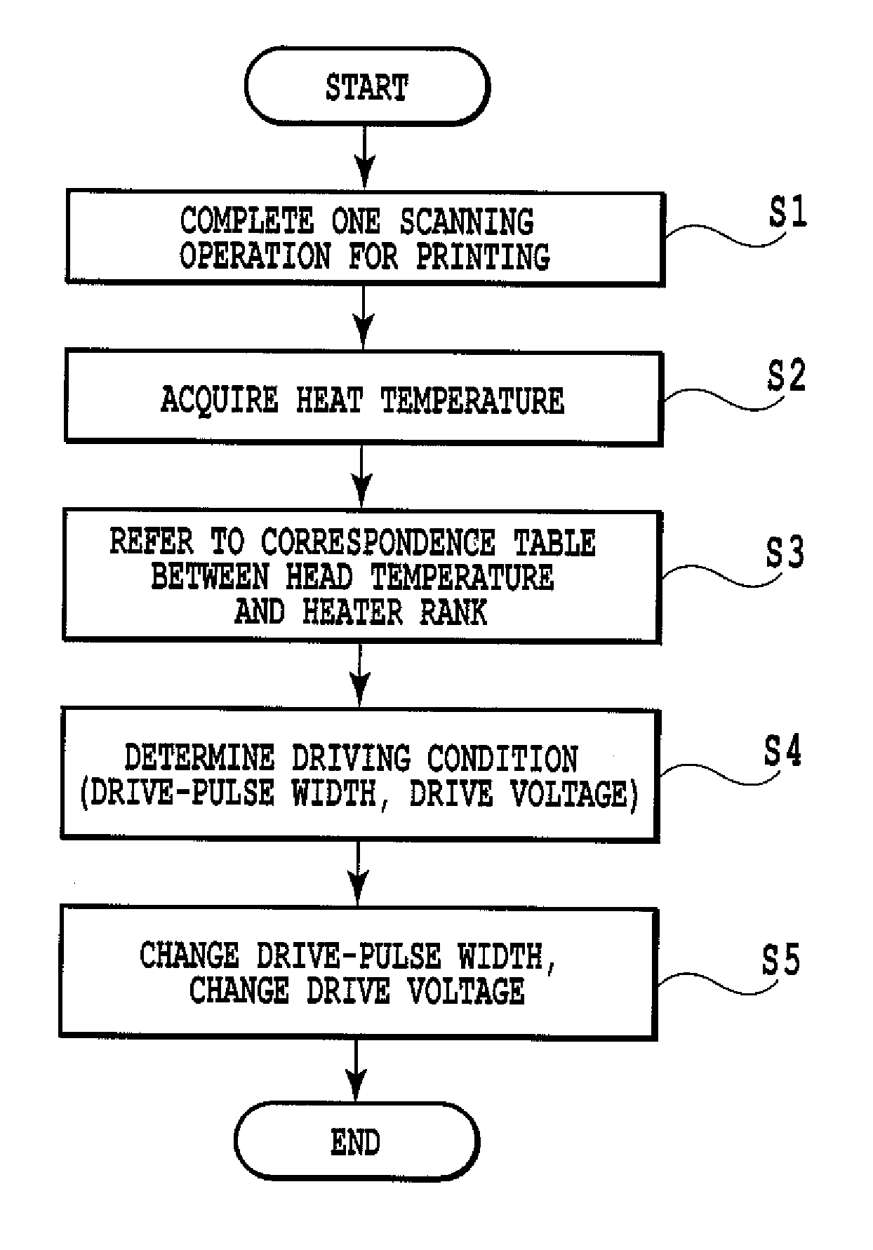
[0059]Descriptions will be provided below for embodiments of the present invention by referring to the drawings.

1. Basic Configuration

1.1 Outline of Printing System

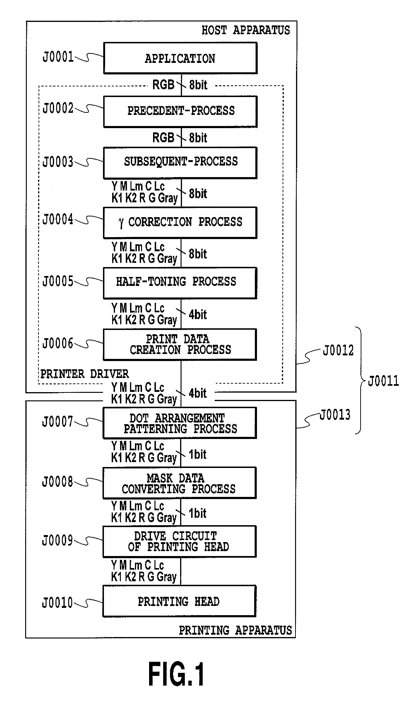
[0060]FIG. 1 is a diagram for explaining a flow in which image data are processed in a printing system to which an embodiment of the present invention is applied. This printing system J0011 includes a host apparatus J0012 which generates image data indicating an image to be printed, and which sets up a user interface (UI) for generating the data and so on. In addition, the printing system J0011 includes a printing apparatus J0013 which prints an image on a printing medium on the basis of the image data generated by the host apparatus J0012. The printing apparatus J0013 performs a printing operation by use of 10 color inks of cyan (C), light cyan (Lc), magenta (M), light magenta (Lm), yellow (Y), red (R), green (G), black 1 (K1), black 2 (K2) and gray (Gray). To this end, a printing head H1001 for ejecting these 10 color i...


PUM


Abstract

The present invention provides an ink jet printing apparatus and an ink jet printing method which are capable of stabilizing the amount of ink ejection and of printing a high-definition image by selecting a driving condition with heat conductivity of an electrothermal converter being taken into consideration. The heat conductivity from a heater to ink is classified into heater ranks, and, on the basis of the heater rank, a voltage of a drive pulse to be applied to the heater is changed.

Description

BACKGROUND OF THE INVENTION[0001]1. Field of the Invention[0002]The present invention relates to an ink jet printing apparatus configured to perform printing by ejecting ink, and also relates to an ink jet printing method.[0003]2. Description of the Related Art[0004]An ink jet printing method configured to eject ink from an ink jet printing head to a printing medium and thereby to print an image on the printing medium has heretofore been known. This printing method has advantages including high-speed printing, high-density printing, and ease of color-image printing.[0005]A typical ink jet printing head applies a method of ejecting ink from an ink ejection port by utilizing heat generation of an electrothermal converter (a heater). The printing head of this type is configured to apply a voltage to the heater to generate heat, to make the ink inside ink passage foam by use of that heat energy, and to eject the ink out of the ink ejection port by use of that foaming energy.[0006]The am...

Claims


Application Information

Patent Timeline
Patent Type & Authority Patents(United States)
IPC IPC(8): B41J29/38
CPCB41J2/04541B41J2/04553B41J2/04563B41J2/04565B41J2/0458B41J29/38B41J2/0459B41J2/04591B41J2/04598B41J2/1752B41J29/02B41J2/04588B41J19/207
Inventor TAKAMIYA, HIDEAKINISHIKORI, HITOSHIIDE, DAISAKUTAJIKA, HIROSHISATO, TAKASHI
Owner CANON KK
Why Eureka
Try Eureka