Switching electrode and resistance welding device using same, spot welding device and spot welding method

Active Publication Date: 2015-05-21
HONDA MOTOR CO LTD
View PDF7 Cites 13 Cited by
  • Summary
  • Abstract
  • Description
  • Claims
  • Application Information

AI Technical Summary

Benefits of technology

[0036]According to the invention, it is possible to provide a switching electrode which has a small variation in resistance value even when a large amount of current is repeatedly cut off and can allow a stable amount of current to flow even when it is continuously used. In

Problems solved by technology

Therefore, when welding is performed so that the nugget is generated around the center of the work, the nugget is not sufficiently grown at the interface between the thinnest plate and the adjacent plate and it is difficult to sufficiently join the thinnest plate and the adjacent plate.
However, a large amount of current flows in the resistance welding.
Therefor

Method used


Image

  • Switching electrode and resistance welding device using same, spot welding device and spot welding method
  • Switching electrode and resistance welding device using same, spot welding device and spot welding method
  • Switching electrode and resistance welding device using same, spot welding device and spot welding method

Examples


Example

First Embodiment

[0063]Hereinafter, an embodiment of the invention will be described with reference to the drawings.

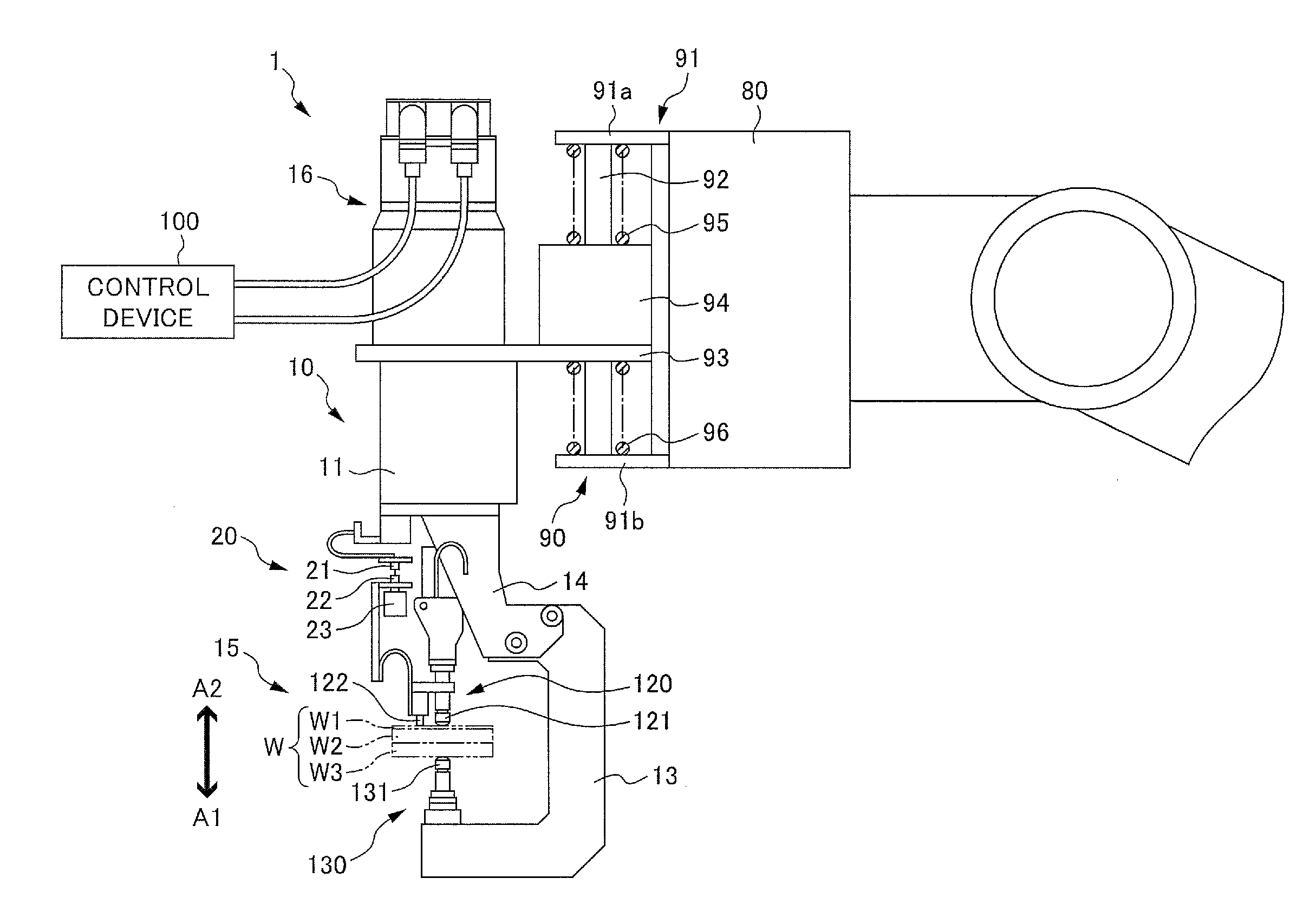
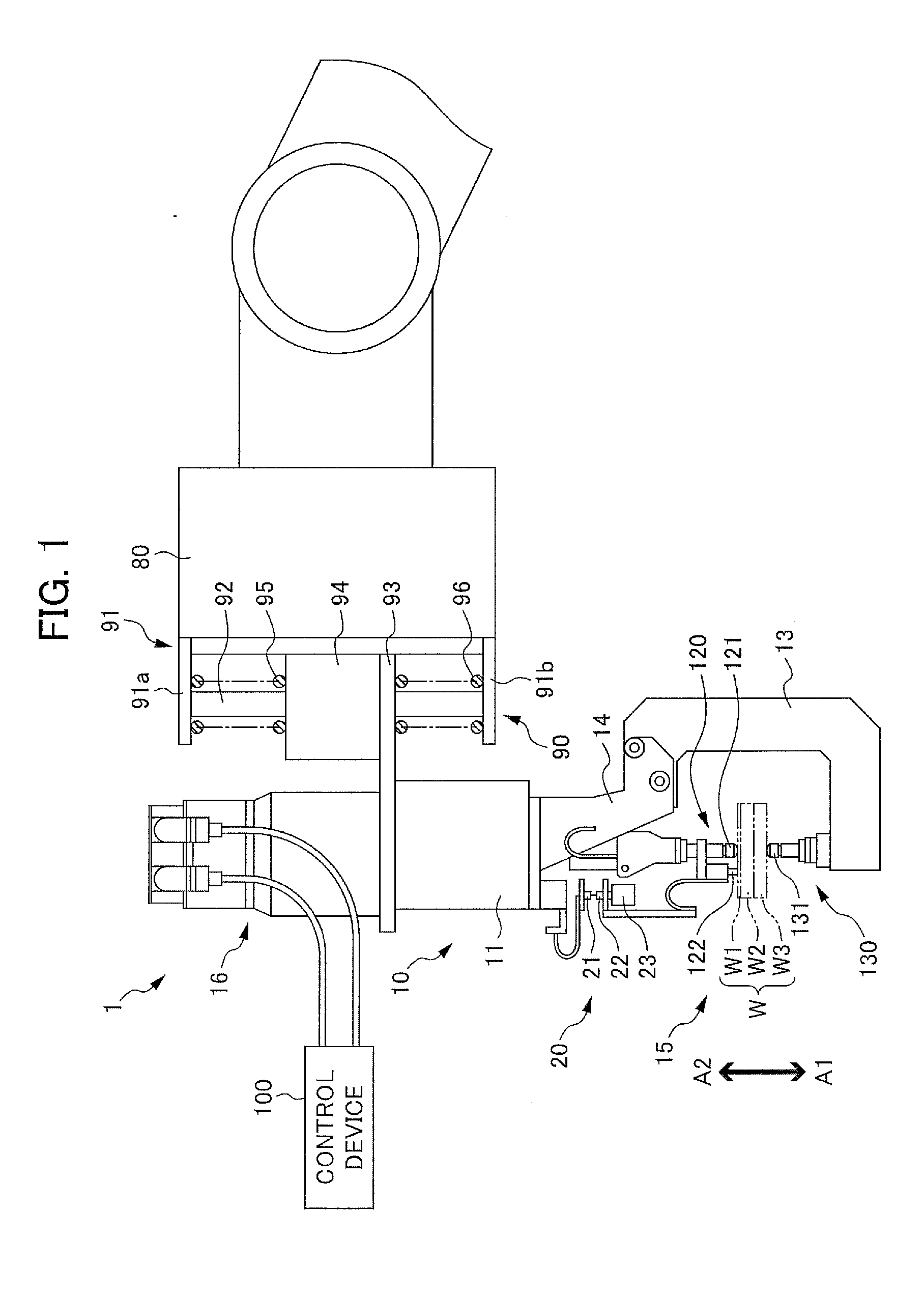
[0064]FIG. 1 is a side view illustrating the structure of a spot welding device using a switch including the set of switching electrodes according to an embodiment of the invention. A spot welding device 1 is an electric-powered spot welding device which is attached to the leading end of a robot arm 80.

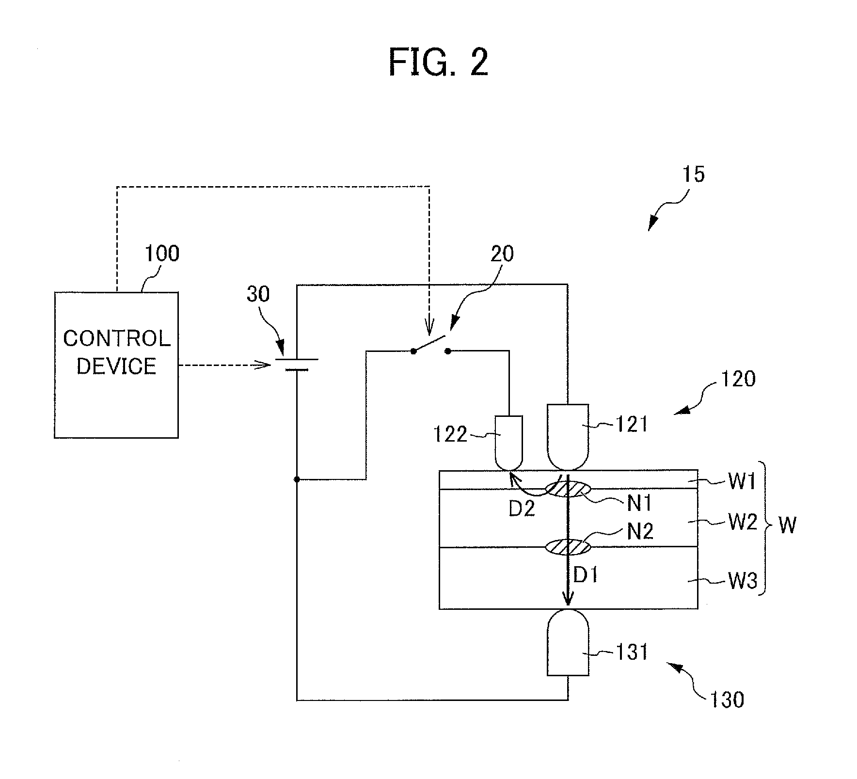
[0065]The spot welding device 1 interposes a work W obtained by overlapping a plurality of plates W1 (thin plate), W2 (thick plate), and W3 (thick plate) between a plurality of electrodes, which will be described below, applies pressure to the work W, and applies a voltage between the electrodes in this state to weld the work W.

[0066]The spot welding device 1 includes a spot welding gun 10 that is supported by a supporting portion 90 provided at the leading end of the robot arm 80 and a control device 100 that controls the spot welding gun 10.

[0067]The supporting portion ...

Example

Second Embodiment

[0110]Next, another embodiment of the invention will be described with reference to FIGS. 5 to 9.

[Structure of Spot Welding Device 1]

[0111]FIG. 5 is a side view illustrating the structure of a spot welding device according to an embodiment of the invention. A spot welding device 1 according to this embodiment is an electric-powered spot welding device that is attached to the leading end of a robot arm 80.

[0112]The spot welding device 1 interposes a work W obtained by overlapping a plurality of plates between a plurality of electrodes, which will be described below, applies pressure to the work W, and applies a voltage between the electrodes in this state to weld the work W. The spot welding device 1 according to this embodiment includes three or more plates and is suitably used to weld the work W in which the thinnest plate is arranged on the outermost side. In this embodiment, a work W in which a thinnest plate W1, a plate W2 (thick plate), and a plate W3 (thick pl...


PUM

PropertyMeasurementUnit
Fractionaaaaaaaaaa
Fractionaaaaaaaaaa
Surface roughnessaaaaaaaaaa

Abstract

The invention provides a switching electrode which has a small variation in resistance value even when a large amount of current is repeatedly cut off and can carry a stable amount of current even when it is continuously used. In the invention, the switching electrode is used in a switch which includes a first switching electrode tip (21) and a second switching electrode tip (22), brings the first switching electrode tip (21) and the second switching electrode tip (22) into surface contact with each other to carry a current, and separates the first switching electrode tip (21) and the second switching electrode tip (22) to cut off the current. At least one of contact surfaces of the first switching electrode tip (21) and the second switching electrode tip (22) is a flat surface having an uneven portion.

Description

TECHNICAL FIELD[0001]The present invention relates to a switching electrode and a resistance welding device using the switching electrode. More particularly, the invention relates to a switching electrode that is used in a switch which includes a pair of electrodes, brings the pair of electrodes into surface contact with each other to carry a current, and separates the pair of electrodes to cut off the current and a resistance welding device using the switching electrode.[0002]In addition, the invention relates to a spot welding device and a spot welding method. More particularly, the invention relates to a spot welding device and a spot welding method that weld a work in which a plate with a minimum thickness is arranged on the outermost side.BACKGROUND ART[0003]In the related art, spot welding (which is also referred to as “resistance welding”) has been used to join a work obtained by overlapping a plurality of plates. In spot welding, the overlapped work is interposed between a p...

Claims


Application Information

Patent Timeline
IPC IPC(8): B23K11/16B23K11/24B23K11/30B23K11/11
CPCB23K11/16B23K11/3009B23K11/24B23K11/11B23K11/115H01H1/06B23K11/314B23K11/36
Inventor MORITA, TAKAHIROMIYASAKA, SHINICHIHIRUMA, YOSUKEGOTO, AKIRAIKEDA, TATSURO
Owner HONDA MOTOR CO LTD
Why Eureka
Try Eureka