Systems and Methods for On-Site Mixing and Dispensing of a Reducing Agent Solution for Use with a Diesel Catalytic Converter

a technology of reducing agent and diesel catalytic converter, which is applied in the direction of liquid transfer device, process and machine control, instruments, etc., can solve the problems of increasing the cost of emissions, increasing the emissions of nitrogen oxides, and creating extra emissions of certain pollutants, so as to reduce the corrosive character of aus compounds, eliminate or reduce the effect of emissions

Active Publication Date: 2011-06-02
BRAMMELL JACK R
View PDF14 Cites 29 Cited by
  • Summary
  • Abstract
  • Description
  • Claims
  • Application Information

AI Technical Summary

Benefits of technology

[0015]In summary, therefore, the systems and methods of the present invention seek to address at least four specific problems that are present in the field. First, the presently described system eliminates, or at least reduces, concerns surrounding the corrosive character of the AUS compound by maintaining it in its component form up to the point of dispensing into the diesel powered vehicle. Second, the method of the present invention eliminates, or significantly reduces many of the transportation costs associated with the delivery of the fully formulated solution to a fuel depot or other dispensing station. Third, in the process of producing the solution on-site, the systems and methods of the present invention eliminate, or significantly reduce, the costs associated with packaging the solution for sale and delivery. Finally, the systems and methods of the present invention eliminate, or significantly reduce, the need for a number of additional dispensing devices, such as those that might be required to dispense the solution from fifty-five gallon drums or the like. The above described problems, addressed by the present invention, are not adequately addressed with the delivery and dispensing of the ready-made dilute solution that comes from a chemical or other manufacturing (blending) facility. The present invention addresses each of these problems by eliminating or mitigating the difficulties and significant expenses associated with handling, packaging, and transporting the product up to the point in the process where it is directly dispensed into the motor vehicle.

Problems solved by technology

Recent efforts to improve the fuel efficiency of diesel engines have been successful but often at the cost of increasing emissions, especially nitrogen oxide ( ) emissions.
These reducing systems were developed in response to a number of the newer processes that give diesel engines greater fuel economy but which as a result create extra emissions of certain pollutants.
High compression ratios and lean air-fuel mixtures result in higher combustion temperatures, which in turn result in more nitrogen oxides and particulate matter being released into the gaseous exhaust system.
While the particulate matter may typically be controlled with higher injection pressures and particulate filters, limiting the emissions can be more problematic.
However, the solution can be corrosive for a number of metals and must be stored and transported using containers, conduits, valves, and fittings made up of certain non-corrosive materials.
Most SCR systems currently in use and in development tend to be sensitive to chemical impurities in the urea solution.
Unfortunately, it is this dilute solution that provides the most corrosive composition to the various metals that it might come into contact with and which requires the use of special storage containers and dispensing conduits.
It would be desirable if this mixing of the dilute solution and the subsequent dispensing of the dilute solution could occur on an as-needed basis as opposed to requiring the maintenance of a supply that degrades over time, and potentially causes corrosive effects throughout the storage and delivery system.

Method used


Image

  • Systems and Methods for On-Site Mixing and Dispensing of a Reducing Agent Solution for Use with a Diesel Catalytic Converter
  • Systems and Methods for On-Site Mixing and Dispensing of a Reducing Agent Solution for Use with a Diesel Catalytic Converter
  • Systems and Methods for On-Site Mixing and Dispensing of a Reducing Agent Solution for Use with a Diesel Catalytic Converter

Examples


Embodiment Construction

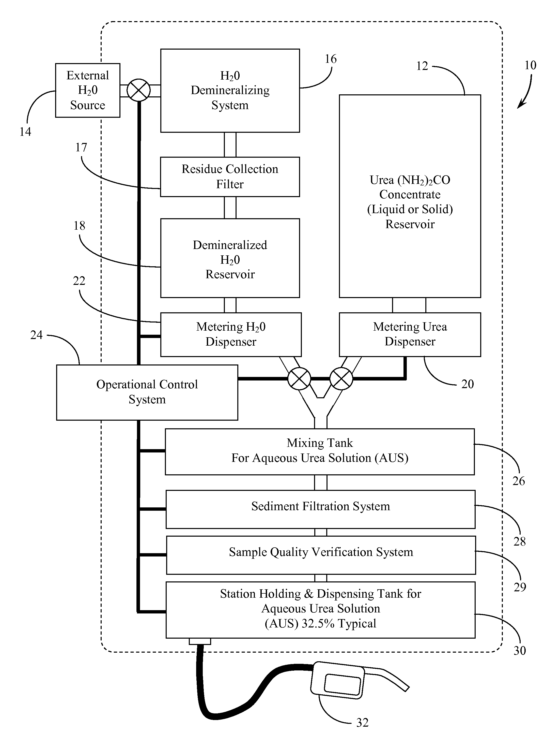
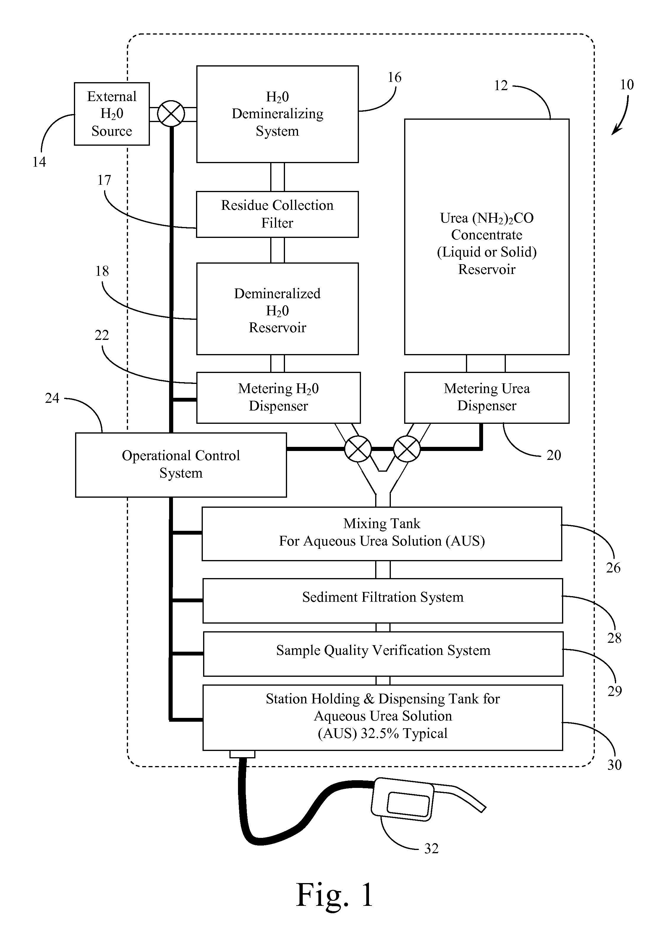
[0019]The systems and methods of the present invention are generally disclosed by reference to the attached Drawing Figures, within which each of the components are commonly referenced as follows:

COMPONENT LISTING

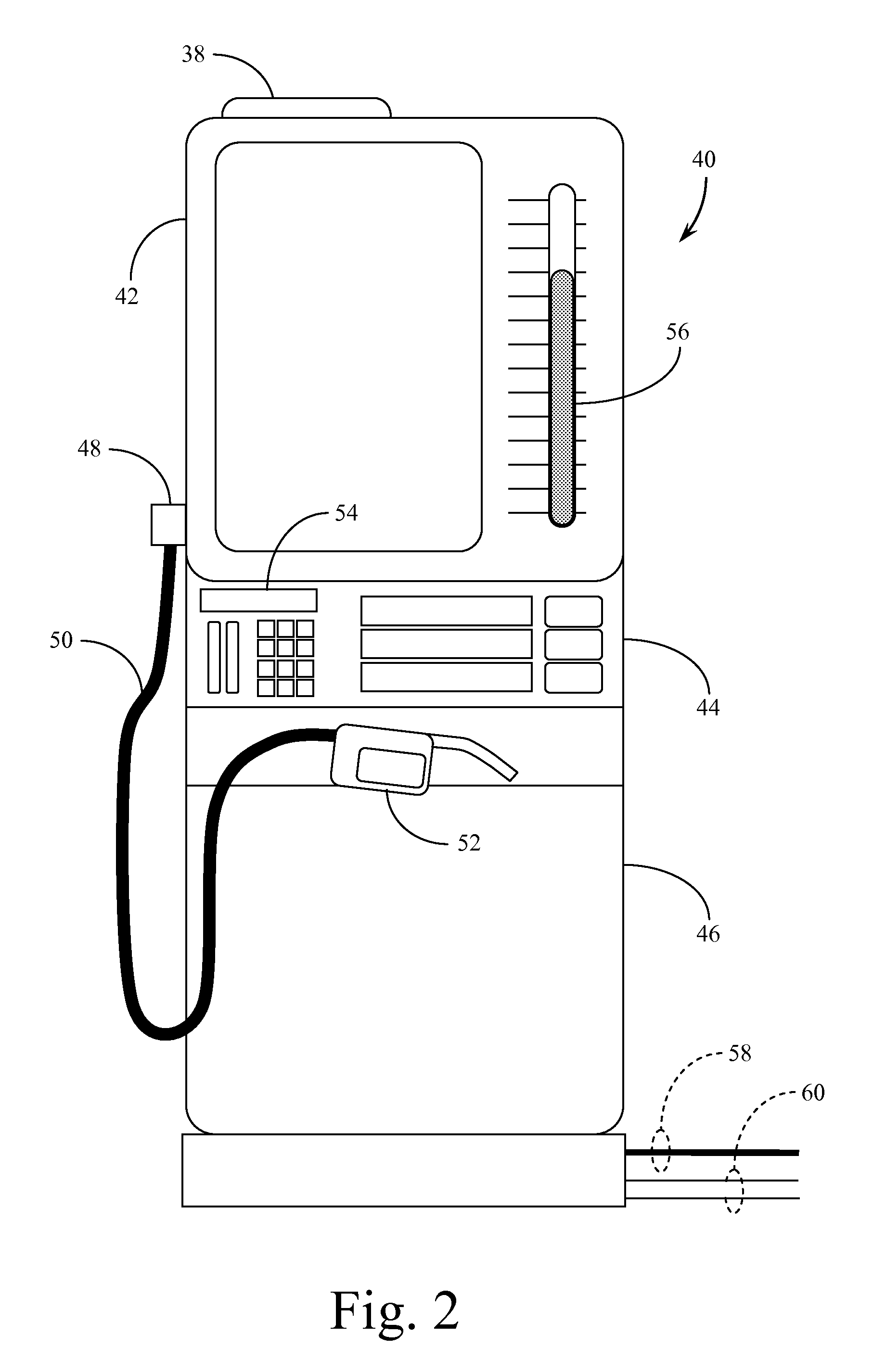
[0020]10 mixing and dispensing unit[0021]12 concentrated urea reservoir[0022]14 external source[0023]16 de-mineralizing system[0024]18 demineralized reservoir[0025]20 metering urea dispenser[0026]22 metering dispenser[0027]24 operational control system[0028]26 mixing tank for aqueous urea solution (AUS)[0029]28 sediment filtration system[0030]29 sample quality verification system[0031]30 station holding and dispensing tank for AUS[0032]32 dispensing valve / nozzle[0033]38 urea reservoir access lid[0034]40 mixing / dispensing terminal[0035]42 reservoir tank section of terminal[0036]44 electronic control section of terminal[0037]46 terminal base support structure[0038]48 dispensing hose connector[0039]50 dispensing hose[0040]52 dispensing nozzle[0041]54 electronic control data in...


PUM


Abstract

Systems and methods for mixing and dispensing an aqueous urea solution at the point of delivery to diesel powered vehicles. A stand alone terminal or modular unit that mixes and dispenses the dilute solution on an as-needed batch basis. Each delivery terminal includes a dry or concentrated liquid urea reservoir, and a metering urea dispenser, along with a parallel demineralized water reservoir and a metering water dispenser. The demineralized water may be provided directly from an external source or the system may include a demineralizing component. The metered dispensing of the urea and the water into a mixing tank to produce the aqueous urea solution (AUS) is controlled through an electronic control system. From the mixing tank the system directs the solution through a sediment filtration system before retaining the mixed and filtered solution in a terminal holding and dispensing tank.

Description

CROSS REFERENCES TO RELATED APPLICATIONS[0001]This application claims the benefit under Title 35 United States Code §119(e) of U.S. Provisional Application 61 / 263,268 filed Nov. 20, 2009, the full disclosure of which is incorporated herein by reference.BACKGROUND OF THE INVENTION[0002]1. Field of the Invention[0003]The present invention relates generally to systems and methods for making and dispensing chemical solutions for use in conjunction with internal combustion engines. The present invention relates more specifically to systems and methods for making a dilute chemical solution from a liquid solvent (water) and either a dry composition (urea) or a concentrated solution (urea), at a point immediately prior to dispensing the dilute solution into a vehicle powered by an internal combustion (diesel) engine.[0004]2. Description of the Related Art[0005]Efforts are continuously being made to reduce emissions associated with the burning of hydrocarbon fuels in internal combustion engi...

Claims


Application Information

Patent Timeline
Patent Type & Authority Applications(United States)
IPC IPC(8): F01N3/10
CPCB67D7/02G05D11/132B67D7/744F01N2610/02
Inventor BRAMMELL, JACK R.
Owner BRAMMELL JACK R
Why Eureka
Try Eureka