Fuel gas production method and apparatus

a fuel gas and production method technology, applied in the direction of sustainable manufacturing/processing, instruments, separation processes, etc., can solve the problem of unclean exhaust gas and achieve the effect of producing hydrogen-rich fuel gas efficiently

Inactive Publication Date: 2008-04-08
SUMITOMO SEIKA CHEM CO LTD
View PDF4 Cites 12 Cited by
  • Summary
  • Abstract
  • Description
  • Claims
  • Application Information

AI Technical Summary

Benefits of technology

[0013]A main object of the present invention is to provide a fuel gas production method and apparatus without using any off gas holder in which the exhaust gas is clean, and it is possible to produce a hydrogen-rich fuel gas efficiently.

Problems solved by technology

Therefore, the exhaust gas is not clean.

Method used


Image

  • Fuel gas production method and apparatus
  • Fuel gas production method and apparatus
  • Fuel gas production method and apparatus

Examples


Embodiment Construction

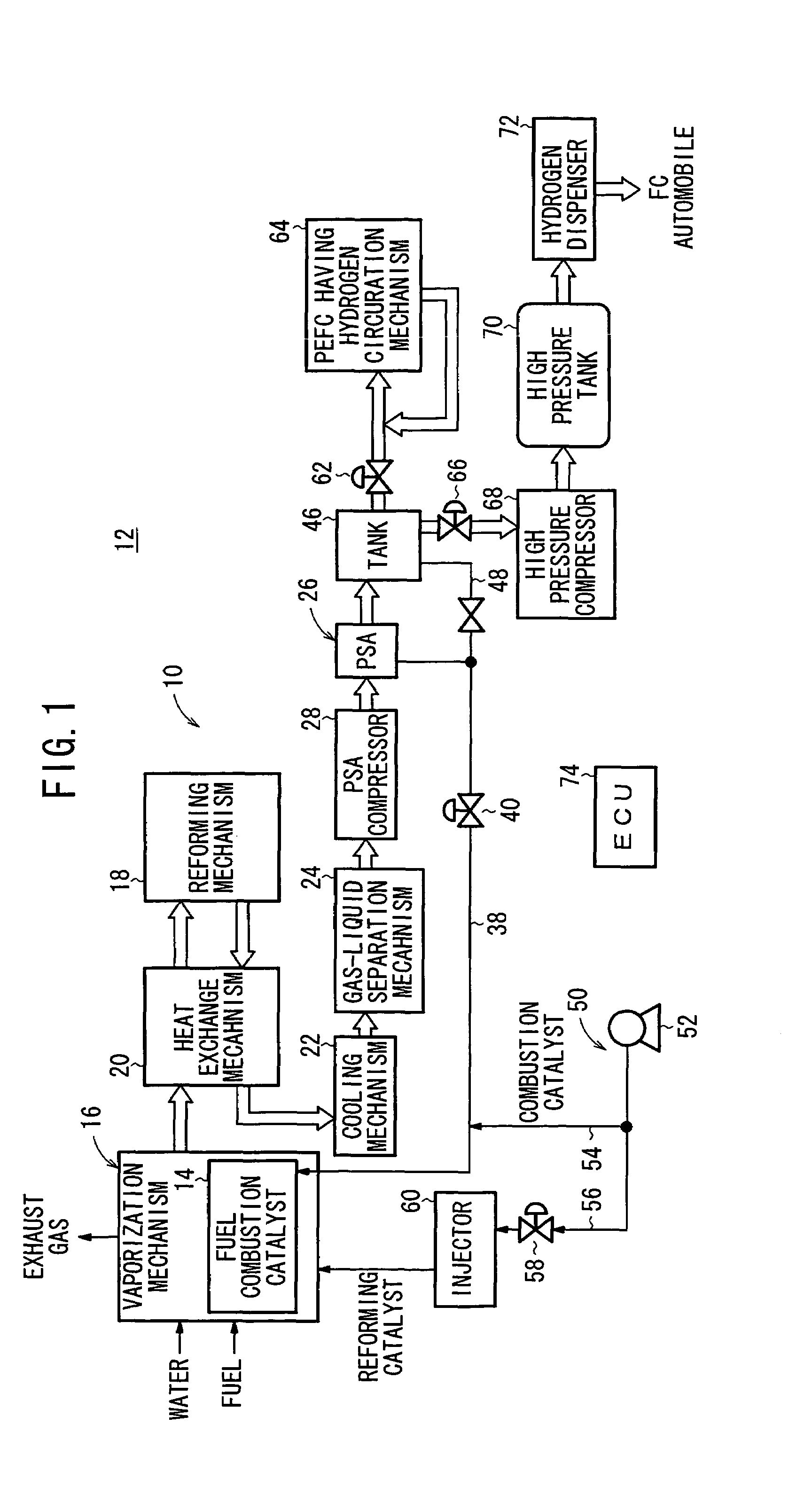
[0028]FIG. 1 is a diagram schematically showing a fuel gas supply system 12 including a fuel gas production apparatus 10 according to an embodiment of the present invention.

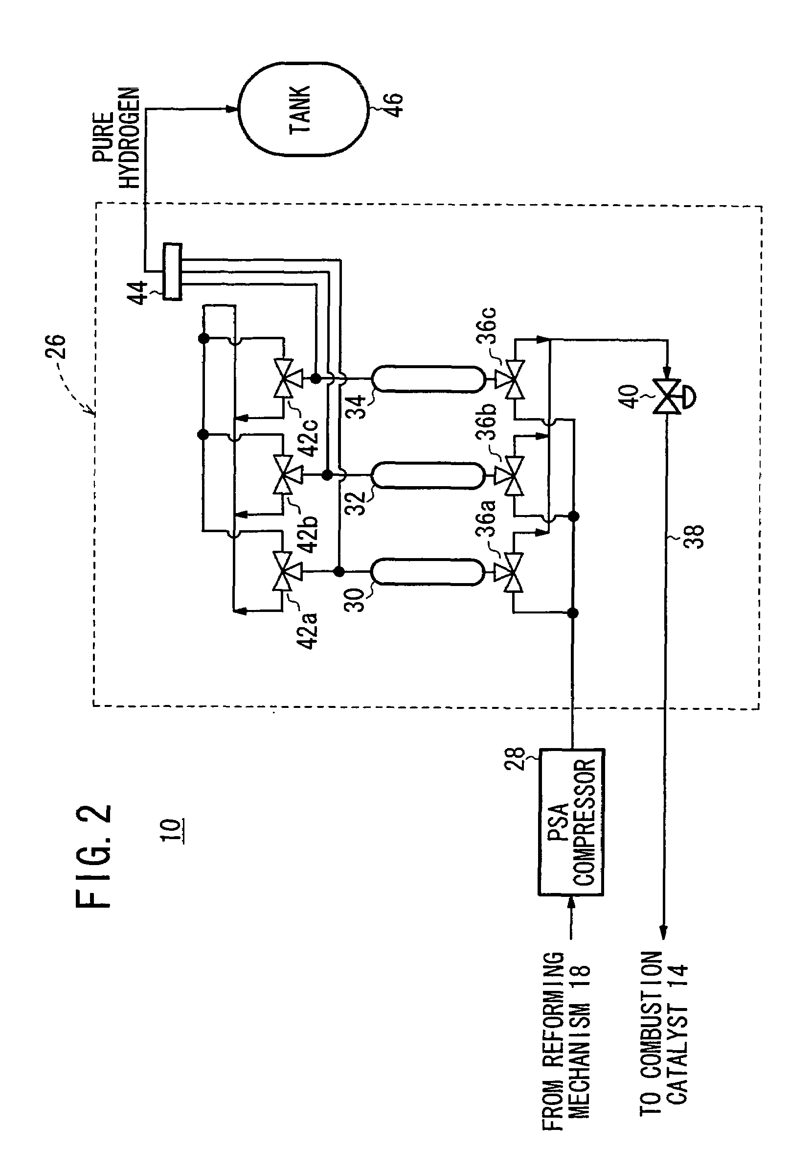
[0029]The fuel gas production apparatus 10 includes a vaporization mechanism 16 having a combustion catalyst (heating unit) 14 for vaporizing a fuel. At the downstream of the vaporization mechanism 16, a reforming mechanism 18 is provided for obtaining a reformed gas from the fuel. A heat exchange mechanism 20 is provided between the vaporization mechanism 16 and the reforming mechanism 18. The heat exchange mechanism 20 heats the reforming mechanism 18 by exchanging the heat between the vaporized fuel and the reformed gas. At the downstream of the heat exchange mechanism 20, a cooling mechanism 22 is provided for cooling the reformed gas after the heat exchange has been performed. At the downstream of the cooling mechanism 22, a gas-liquid separation mechanism 24 is provided for separating gas component and wate...


PUM

PropertyMeasurementUnit
temperatureaaaaaaaaaa
pressureaaaaaaaaaa
flow rateaaaaaaaaaa

Abstract

A fuel gas production apparatus includes a vaporization mechanism, a reforming mechanism, a PSA mechanism, a supply passage, a combustion air supply mechanism and an ECU. The vaporization mechanism has a combustion catalyst for vaporizing a fuel. The reforming mechanism reforms the vaporized fuel to obtain a reformed gas. The PSA mechanism refines the reformed gas by removing impurities to produce a fuel gas. The impurities removed by the PSA mechanism are continuously supplied as a heat source fuel to the vaporization mechanism through the supply passage. The combustion air supply mechanism supplies combustion air to the vaporization mechanism. The ECU controls the amount of the combustion air supplied to the vaporization mechanism synchronously with the change in the amount of heat energy of the impurities supplied to the vaporization mechanism.

Description

BACKGROUND OF THE INVENTION[0001]1. Field of the Invention[0002]The present invention relates to a fuel gas production method and apparatus for reforming a fuel containing hydrocarbon or alcohol to produce a hydrogen-rich fuel gas.[0003]2. Description of the Related Art[0004]For example, a solid polymer electrolyte fuel cell employs a membrane electrode assembly (MEA) which includes two electrodes (anode and cathode), and an electrolyte membrane interposed between the electrodes. The electrolyte membrane is a polymer ion exchange membrane. The membrane electrode assembly is interposed between a pair of separators. The membrane electrode assembly and the separators make up a unit cell for generating electricity. Generally, a plurality of the unit cells are stacked together to form a fuel cell stack. The fuel cell stack has been used widely in various applications including stationary and mobile applications.[0005]In the unit cell, a fuel gas such as a gas chiefly containing hydrogen ...

Claims


Application Information

Patent Timeline
Patent Type & Authority Patents(United States)
IPC IPC(8): C01B3/26B01J8/04B01D53/047C01B3/38C01B3/56H01M8/06H01M8/10
CPCB01D53/047C01B3/38C01B3/56B01D53/053B01D2256/16B01D2258/0208B01D2259/403C01B2203/0233C01B2203/043C01B2203/047C01B2203/0475C01B2203/066C01B2203/0811C01B2203/0822C01B2203/0827C01B2203/0883C01B2203/1241C01B2203/1695Y02P20/10
Inventor OKADA, HIKARUMACHIDA, HIROSHIYOSHIDA, NOBUYOSHI
Owner SUMITOMO SEIKA CHEM CO LTD
Why Eureka
Try Eureka