Magnetic device

a magnetic device and magnetic core technology, applied in the direction of transformer/inductance details, inductance with magnetic core, basic electric elements, etc., can solve the problems of reducing the thickness, reducing the inductance, and achieving sufficient characteristi

Active Publication Date: 2008-04-29
PANASONIC CORP
View PDF12 Cites 8 Cited by
  • Summary
  • Abstract
  • Description
  • Claims
  • Application Information

AI Technical Summary

Benefits of technology

[0015]The present invention intends to solve the foregoing subject and provides a magnetic device capable of obtaining a sufficient inductance value and an excellent in high frequency characteristic even when it is with smaller size and lower profile.

Problems solved by technology

However, the structure is intended for the size reduction of the magnetic device but not intended for the reduction of the thickness.
Further, since the magnetic channel length in a mixture of the magnetic powder and the resin is long, it can not be said that sufficient characteristic can be obtained and it still leaves a subject.
As a result, when it is used as it is, the inductance lowers greatly by magnetic saturation tending to worsen the DC current superimpose characteristic.
However, since the saturated magnetic flux density is low, it is difficult to cope with high current.
However, the dust core involves a problem that the core loss is large.
Accordingly, since the permeability is deteriorated along with increase in the distortion as the magnetic body, the hysteresis loss increases.
However, for coping with further higher current, higher frequency and lower profile for power sources, the existent constitution involves a problem that it can not sufficiently insure the lower resistance, higher inductance value or high frequency characteristic of conductors.

Method used


Image

  • Magnetic device
  • Magnetic device
  • Magnetic device

Examples


embodiment 1

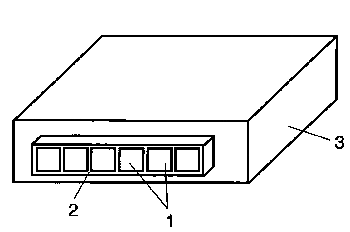
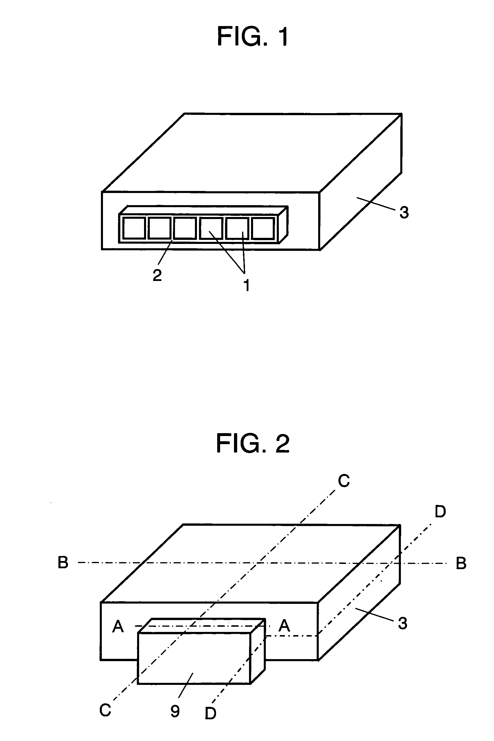
[0026]Embodiment 1 is to be described with reference to FIG. 1, FIG. 2 and FIG. 3A to FIG. 3C.

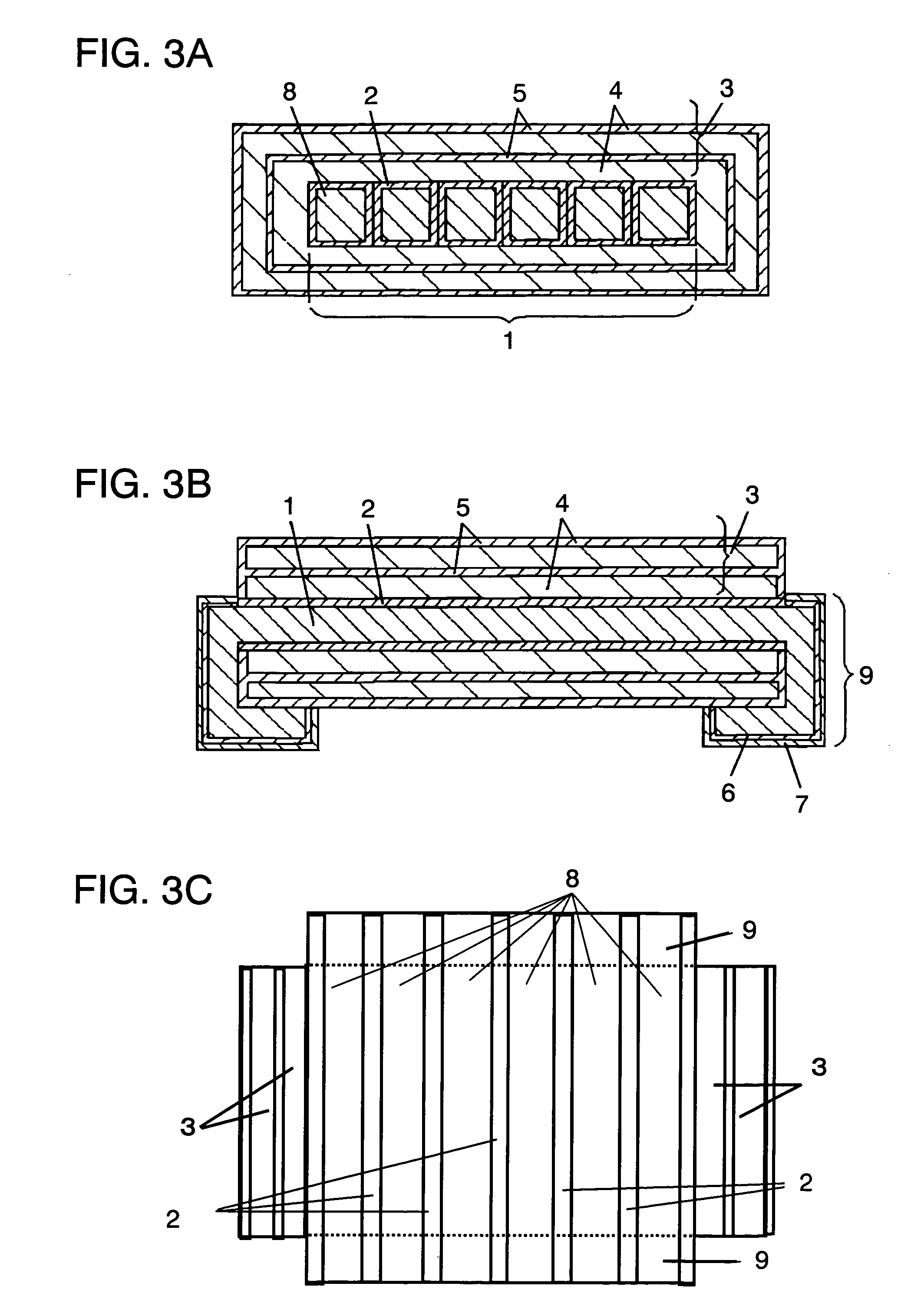
[0027]The coil conductor 1 comprises conductors 8 made of a metal material having low resistance covered with an insulation film 2 arranged in plurality.

[0028]In FIG. 3A to FIG. 3C, conductors 8 each covered with the insulation film 2 are arranged to be parallel to C-C direction in the same plane.

[0029]In the present embodiment six conductors 8 are employed, however, the number of conductors may be changed.

[0030]The reason of using such a constitution is as described below.

[0031]Generally, in a case where the coil conductor 1 is constituted with one conductor 8 by fabricating a metal material having low resistance such as a copper sheet or a copper wire, the current flowing through the conductor 8 flows concentrically at the surface of the conductor 8 as the frequency is higher by the skin effect. As a result, an apparent resistance value (Rac) of the coil conductor 1 increases at a high fr...

embodiment 2

[0057]Description is to be made to Embodiment 2 with reference to FIG. 2, FIG. 4 and FIG. 5.

[0058]The constitutions identical with those in Embodiment 1 carry the same reference numerals for which detailed descriptions will be omitted. Conductors 8 of a coil conductor 1 are covered each with insulation film 2. A coil conductor 1 shown in FIG. 4 is constituted with two stacked conductor layers. The conductor layer includes conductors 8 having rectangular cross sectional shapes are arranged in the same plane being parallel to the mounting surface.

[0059]A coil conductor 1 shown in FIG. 5 is different from FIG. 4 in that conductors 8 are arranged in the parallel direction to line D-D shown in FIG. 2.

[0060]The material for the conductor 8 is preferably copper, silver or aluminum of low specific resistivity, or it may be an alloy containing them. Further, the insulation film layer 2 electrically insulates each of the conductors 8.

[0061]Since a connection terminal 9 is formed contiguous wi...

embodiment 3

[0079]Embodiment 3 is to be described with reference to FIG. 2 and FIG. 6.

[0080]As shown in FIG. 2 and FIG. 6, a coil conductor 1 of a magnetic device comprises two rectangular conductors 8 formed by dividing in the vertical direction relative to the mounting surface. Further, since the basic constitution of this embodiment is identical with those of Embodiments 1 and 2, detailed descriptions therefor will be omitted.

[0081]However, this is different from Embodiments 1 and 2 in that a slit 11 is formed in the magnetic layer 4 cutting the magnetic layer 4. The slit 11 can be filled with an insulating material. The slit 11 can suppress the saturation of the magnetic flux and improve the DC superimpose characteristic.

[0082]The operation of the magnetic device having the foregoing constitution is to be described below.

[0083]When a high current is supplied to the coil conductor 1, a strong magnetic flux is generated in the magnetic device to generate a magnetic flux in the direction of th...


PUM

PropertyMeasurementUnit
thicknessaaaaaaaaaa
widthaaaaaaaaaa
thicknessaaaaaaaaaa

Abstract

A magnetic device of smaller size and lower profile comprising a coil conductor of high inductance and low resistance is provided. The magnetic device comprises a coil conductor and a multilayer magnetic layer formed so as to cover the periphery of the coil conductor. Further, a magnetic device having higher inductance value and lower conductor resistance value (AC resistance) by selecting a magnetic layer capable of suppressing the eddy current and having excellent magnetic characteristics even designed with smaller size and lower profile.

Description

FIELD OF THE INVENTION[0001]The present invention relates to a magnetic device used for inductors in electronic equipments.BACKGROUND OF THE INVENTION[0002]In recent years, along with a general trend of reducing the size and the thickness of electronic equipments, it has been strongly demanded to decrease the size and reduce the thickness of the electronic parts or power source devices used for them.[0003]On the other hand, LSI, for example, in CPU have been improved in the operation speed and increased in the degree of integration and a high current is sometimes supplied to a power supply circuit for LSI. Accordingly, it is necessary for inductors such as choke coils used in the power source circuit described above to lower heat generation by decreasing the resistance of coil conductors and suffer from less lowering of the inductance value due to DC super impose (i.e., satisfactory DC superimposing characteristics).[0004]Further, since the working frequency for them has become high...

Claims


Application Information

Patent Timeline
Patent Type & Authority Patents(United States)
IPC IPC(8): H01F5/00H01F17/04H01F27/28H01F17/06H01F27/02H01F27/29
CPCH01F17/06H01F27/027H01F17/04H01F27/292
Inventor MATSUTANI, NOBUYAIMANISHI, TSUNETSUGU
Owner PANASONIC CORP
Why Eureka
Try Eureka