Sensor assembly and method of assembling a sensor module in a transmission

a technology of sensor module and transmission, which is applied in the direction of measuring devices, instruments, structural/machine measurement, etc., can solve the problem that the test stand electrical connector cannot interface with the electrical connector, and achieve the effect of minimizing the installation error

Inactive Publication Date: 2008-07-15
GM GLOBAL TECH OPERATIONS LLC
View PDF3 Cites 5 Cited by
  • Summary
  • Abstract
  • Description
  • Claims
  • Application Information

AI Technical Summary

Benefits of technology

[0004]A sensor assembly is provided with a speed sensor module that is rotatable relative to a bracket between a first position and a second position. The sensor module has a central axis about which it is rotatable. The sensor module need not be translated along the axis to accomplish the rotation; therefore, it may remain installed axially through an aperture of a transmission casing and adjustment between the positions will not involve fluid leakage. The sensor module and the bracket interfit to establish and define both the first and second positions. The sensor module cannot rotate relative to the bracket when interfit with the bracket in the first and second positions. Thus, installation error is minimized. The sensor module is fully operative in both positions. Thus, one position may be optimal for purposes of testing while the other position may be optimal for in-vehicle use with associated packaging issues.

Problems solved by technology

If a different installed position of the sensor module is necessary for a different vehicle model, this may be inconsistent with the test stand design.
For instance, the test stand electrical connectors may not be able to interface with an electrical connector on the sensor module when the sensor module electrical connector is in a different orientation.

Method used


Image

  • Sensor assembly and method of assembling a sensor module in a transmission
  • Sensor assembly and method of assembling a sensor module in a transmission
  • Sensor assembly and method of assembling a sensor module in a transmission

Examples


Embodiment Construction

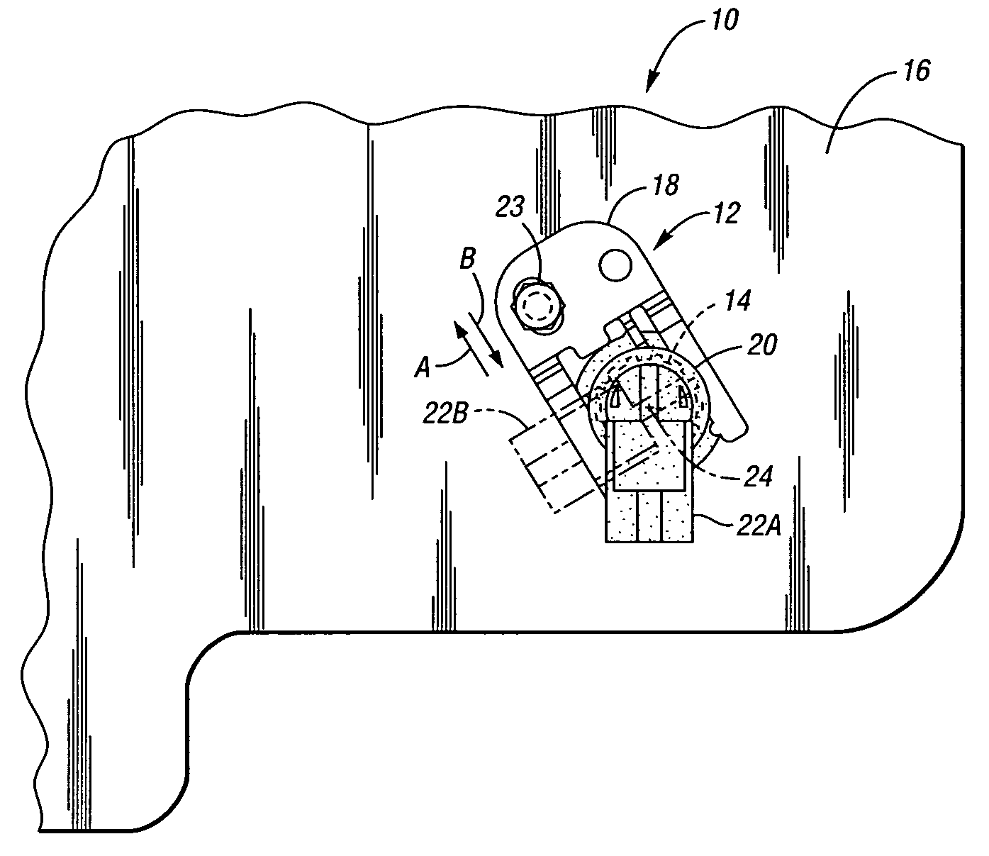
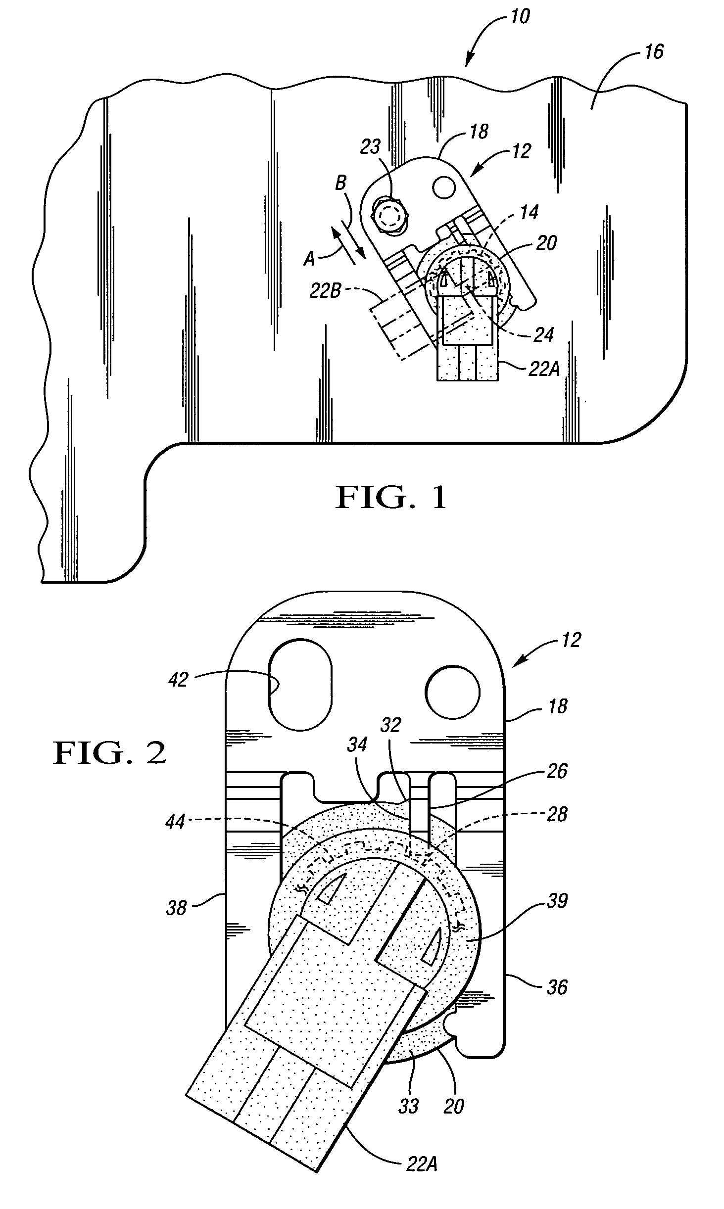
[0011]Referring to the drawings, wherein like reference numbers refer to like components, FIG. 1 schematically shows a transmission 10 having a sensor assembly 12 installed thereon. An aperture 14 extending through a casing 16 of the transmission 10 allows a portion of the sensor assembly 12 to extend within the transmission 10 for sensing rotational speed of an output member (not shown) as is understood by those skilled in the art. The sensor assembly 12 includes a bracket 18 as well as a sensor module 20. Referring to FIG. 3, the sensor module 20 includes a plastic body 19 including a generally cylindrical portion 21 overmolded over a magnetic pickup (not visible within the body 19) and including an electrical connector 25 (see FIG. 4) within an electrical connector portion of the body 19. The body 19 of the sensor module 20 is generally cylindrical so that the sensor module 20 has a central axis 24. The electrical connector portion is shown in a first position in which the electr...


PUM


Abstract

A sensor assembly is provided with a speed sensor module that is rotatable relative to a bracket between first and second positions. The sensor module need not be translated to accomplish the rotation; therefore, it may remain installed through an aperture of a transmission casing and adjustment between the positions will not involve fluid leakage. The sensor module and the bracket interfit to establish and define both the first and second positions. A method of assembling a sensor module in a transmission includes loosening a bolt holding a bracket to a transmission casing, sliding the bracket relative to the sensor module, and then rotating a sensor module between first and second positions without removing or even translating the module in the casing aperture. Preferably, testing of the sensor module occurs when it is in the first position and the second position is an in-use position.

Description

CROSS-REFERENCE TO RELATED APPLICATIONS[0001]This application claims the benefit of U.S. Provisional Application 60 / 756,152, filed Jan. 4, 2006, which is hereby incorporated by reference in its entirety.TECHNICAL FIELD[0002]The invention relates to a sensor assembly for a transmission and a method of assembling a sensor module in a transmission.BACKGROUND OF THE INVENTION[0003]Transmission output speed sensor modules are typically inserted through the transmission casing so that the sensor end is in the immediate proximity of a non-contact ring with protrusions on its perimeter that are detected by the sensor as they pass by it. The sensor is in contact with transmission fluid within the transmission and an electrical connector end is located outside of the transmission casing, with the electrical connector accessible for connection via wiring to an electronic control module. A dedicated opening through the casing is required for the sensor module. Additionally, a bracket that secur...

Claims


Application Information

Patent Timeline
Patent Type & Authority Patents(United States)
IPC IPC(8): G01D21/00G01M99/00
CPCG01P1/026G01P1/00
Inventor LOSCHER, FRANK
Owner GM GLOBAL TECH OPERATIONS LLC
Why Eureka
Try Eureka