AI technical title is built by PatSnap AI team. It summarizes the technical point description of the patent document.
a technology of ink jet printer and ink cartridge, which is applied in the direction of printing, etc., can solve the problems of inability to perform recording operations, inability to effectively prevent adverse effects of recording heads, and inability to absorb ink
Active Publication Date: 2008-07-15
BROTHER KOGYO KK
View PDF33 Cites 16 Cited by
Summary
Abstract
Description
Claims
Application Information
AI Technical Summary
This helps you quickly interpret patents by identifying the three key elements:
Problems solved by technology
Method used
Benefits of technology
Benefits of technology
[0008]If a connection portion where an ink supply tube is connected and accordingly ink may leak is located remote from a portion where a recording head is mounted, then the recording head is effectively prevented from being adversely affected by the ink that may leak from an end of the ink supply tube.
[0009]It is therefore an object of the present invention to provide an ink jet printer which can prevent a recording head from being adversely affected by ink. It is another object of the present invention to provide an ink jet printer which can prevent one or more portions (e.g., an adhered portion or an electronic component) susceptible to ink, from being wetted by the ink.
Problems solved by technology
However, when the above-indicated ink jet printer is checked for maintenance and, for example, the recording head is replaced with a new one, or when the ink supply tube is temporarily detached from a tube joint on the carriage during an assembling operation in a factory, the ink may leak from the ink supply tube and fall onto the carriage.
If the carriage is moved, in a recording operation, with the ink remaining on the carriage, the ink may be moved because of inertia and accordingly the recording head may be wetted by the ink and fail to perform the recording operation.
More specifically described, the ink may wet an adhered portion or portions of the recording head and lower the adhering force, or may wet an electronic component or components such as a flexible flat cable and cause an electric short circuit.
Method used
Image
Click on the blue label to locate the original text in one second.
Reading with bidirectional positioning of images and text.
Examples
first embodiment
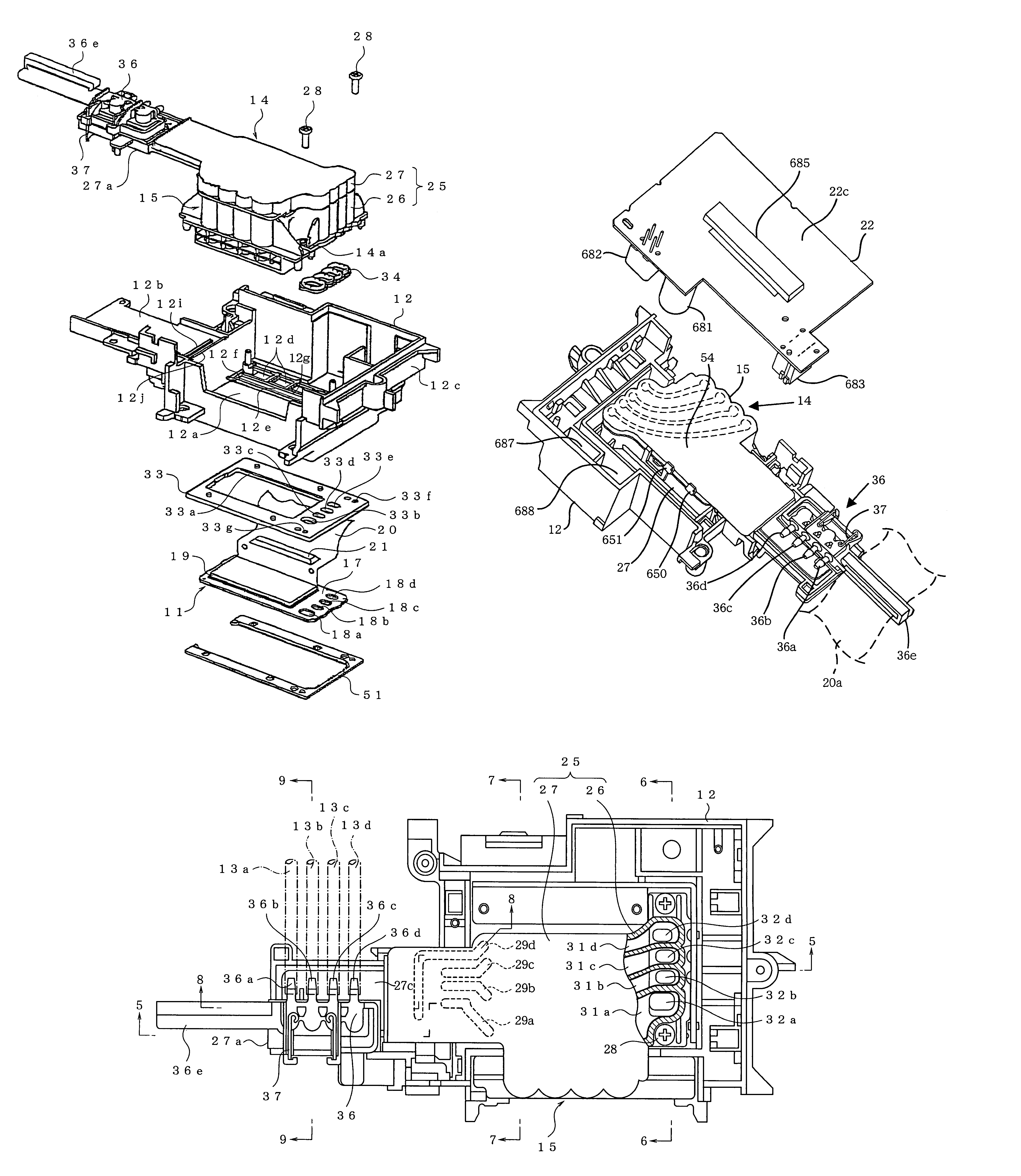
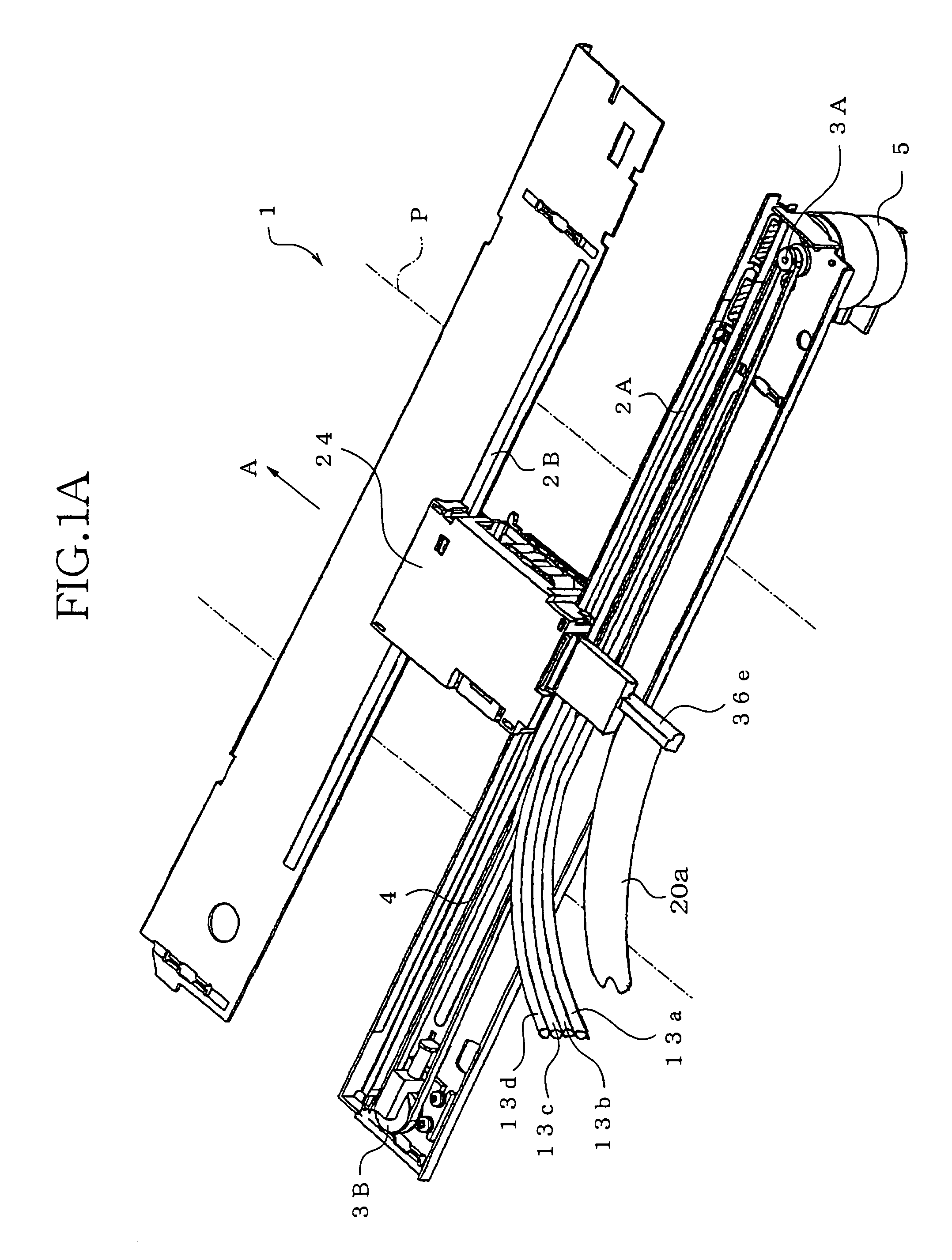
[0160]FIGS. 1A, 2, and 3 show an ink jet printer 1 as the present invention. The ink jet printer 1 includes a recording head 11, a head holder 12, a damping device 14, and a reinforcing frame 33. The head holder 12 holds the recording head 11 and supports the damping device 14, and also functions as a movable carriage.
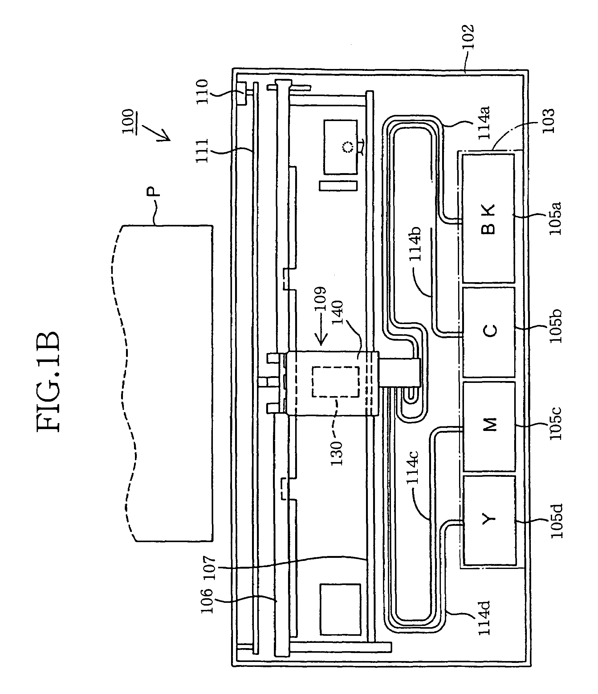
[0161]The head holder 12 as the carriage holds the recording head 11, and is movable relative to a recording sheet P as a sort of recording medium. The recording head 11 is of an ink jet type wherein a droplet of ink is ejected from each of ink ejection nozzles 16a, 16b, 16c, 16d, and has a plate-like shape. The head holder 12 is formed of a synthetic resin, and supports the damping device 14. Four sorts of inks are supplied from four ink storing tanks, not shown, respectively, via respective ink supply tubes 13a, 13b, 13c, 13d, to the damping device 14, and are reserved by the same 14. Then, the four inks are delivered from the damping device 14 to the recording head ...
first modified embodiment
[0230]In the first modified embodiment shown in FIG. 19, the single continuous outer rib 70 shown in FIG. 17 is replaced with a group of (i.e., ten) discontinuous outer ribs 200, 201, 202, 203, 204, 205, 206, 207, 208, 209. The group of outer ribs include a straight rib 200 that is located outside the straight portion 61c of the inner rib 61 and is opposed to the same 61c; two arcuate ribs 202, 203 that are located outside the two arcuate portions 61a, 61b of the inner rib 61, and are opposed to the same 61a, 61b, respectively; two arcuate ribs 204, 205 that are located outside the two arcuate portions 62a, 62b of the inner rib 62, and are opposed to the same 62a, 62b, respectively; two arcuate ribs 206, 207 that are located outside the two arcuate portions 63a, 63b of the inner rib 63, and are opposed to the same 63a, 63b, respectively; two arcuate ribs 208, 209 that are located outside the two arcuate portions 64a, 64b of the inner rib 64, and are opposed to the same 64a, 64b, res...
PUM
Abstract
An ink jet printer including a stationary frame; a tank supporter which is provided in the stationary frame and which supports at least one ink storing tank storing at least one sort of ink; a recording head which records an image on a recording medium by ejecting a droplet of the ink, and which has at least one ink flow inlet; at least one ink delivering tank which delivers the ink and has at least one ink flow outlet; at least one ink supply tube which is provided between the tank supporter and the ink delivering tank and through which the ink is supplied from the ink storing tank to the recording head via the ink delivering tank, wherein the delivering tank provides at least a portion of at least one ink delivering channel connecting between the ink supply tube and the recording head; a head holder which includes a main portion holding the recording head and the ink delivering tank, and which is movable relative to the stationary frame so that the recording head records the image on the recording medium; and an ink-contact preventing portion which prevents the ink that leaks from the ink delivering channel, from contacting the recording head.
Description
[0001]The present application is based on Japanese Patent Applications No. 2004-065735 filed on Mar. 9, 2004, No. 2004-065732 filed on Mar. 9, 2004, No. 2004-076062 filed on Mar. 17, 2004, No. 2004-082644 filed on Mar. 22, 2004, No. 2004-082645 filed on Mar. 22, 2004, and No. 2004-207208 filed on Jul. 14, 2004, the contents of which are incorporated herein by reference.BACKGROUND OF THE INVENTION[0002]1. Field of the Invention[0003]The present invention relates to an ink jet printer and particularly to such an ink jet printer in which ink is supplied from an ink storing tank via an ink supply tube to a recording head mounted on a movable head holder.[0004]2. Discussion of Related Art[0005]Recently there has been a demand to decrease a thickness of a carriage for the purpose of decreasing a thickness of an ink jet printer as a whole. That is, there has been a demand to construct an ink jet printer such that no ink storing tanks are mounted on a carriage. To this end, it is needed to ...
Claims
Application Information
Patent Timeline
Application Date:The date an application was filed.
Publication Date:The date a patent or application was officially published.
First Publication Date:The earliest publication date of a patent with the same application number.
Issue Date:Publication date of the patent grant document.
PCT Entry Date:The Entry date of PCT National Phase.
Estimated Expiry Date:The statutory expiry date of a patent right according to the Patent Law, and it is the longest term of protection that the patent right can achieve without the termination of the patent right due to other reasons(Term extension factor has been taken into account ).
Invalid Date:Actual expiry date is based on effective date or publication date of legal transaction data of invalid patent.

