Compact sickle drive for a header of an agricultural plant cutting machine

a cutting machine and compact technology, applied in the direction of mowers, agriculture tools and machines, agriculture, etc., can solve the problems of increasing the possibility of accidentally increasing the risk of vibration at the drive system, and increasing the possibility of accidental pushing down adjacent standing crops

Active Publication Date: 2008-07-22
BLUE LEAF I P INC
View PDF20 Cites 79 Cited by
  • Summary
  • Abstract
  • Description
  • Claims
  • Application Information

AI Technical Summary

Benefits of technology

[0009]According to a preferred aspect of the invention, the compact drive mechanism is adapted to be located beneath, or incorporated into, a floor or pan of a header at a location spaced from the sides or ends of the header, such that cut crops or other plant material can flow over and around the drive mechanism and not be obstructed thereby. The drive mechanism of the invention is preferably configured for driving two knife assemblies of a sickle disposed in end to end relation, reciprocatingly in opposite directions, such that forces generated by the moving masses of the drive mechanism and the two knife assemblies, including forces resulting from moments, are at least substantially completely contained within the structure of the drive mechanism, and therefore are not directed to structure of the header. As a result, large, heavy drive units and support structure adequate for withstanding vibrations and high back and forth forces, are eliminated from the sides or ends of the header, as is timing apparatus for connecting the drives, and the crop dividers on the sides can be narrower.
[0011]Preferably, the two epicyclic drives are mounted in side by side relation, and are connected in reciprocatingly driving relation to two knife assemblies, respectively, preferably supported in end to end relation adjacent to the front edge portion of the floor or pan of a header, for simultaneously moving the knife assemblies reciprocatingly in opposite sideward directions. The timing also causes the eccentric elements of the respective drives to eccentrically rotate in timed relation, such that radial forces generated by imbalances of the respective eccentric elements are also at least substantially cancelled, resulting in the net overall forces and vibrations emanating from the two drives and knife assemblies being greatly reduced or even substantially eliminated.

Problems solved by technology

Disadvantages of the side location include that the header must include significant frame structure for supporting the drive and to withstand forces and vibrations generated thereby.
The end structure or crop divider at the end of the header must also be relatively wide, to accommodate the drive and to direct adjacent standing crops therepast, and increasing the possibility of accidentally pushing down adjacent standing crops.
This typically involves relatively long mechanical drive lines connecting the two drives together, which is disadvantageous as it adds weight, cost and complexity.
These high forces can have at least two negative effects, vibration at the drive system that may be transmitted to other components of the machine, and fatigue failure of the structural components themselves.

Method used


Image

  • Compact sickle drive for a header of an agricultural plant cutting machine
  • Compact sickle drive for a header of an agricultural plant cutting machine
  • Compact sickle drive for a header of an agricultural plant cutting machine

Examples


Embodiment Construction

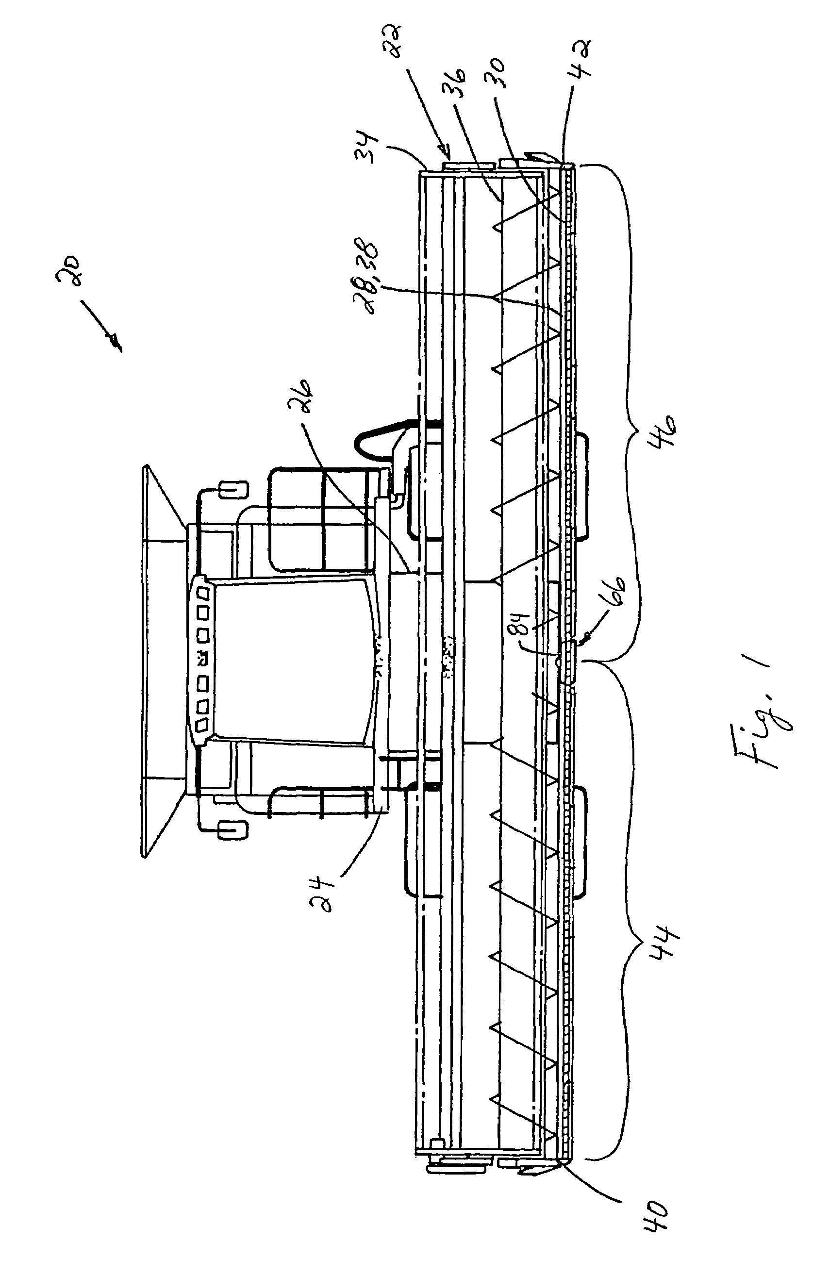
[0042]Turning now to the drawings wherein several preferred embodiments of the invention are shown, in FIG. 1, a conventional, well known agricultural cutting machine, which is a combine 20, is shown including a header 22. Header 22 is shown supported in the conventional, well-known manner on a forward end 24 of combine 20, and is operable for cutting or severing crops such as, but not limited to, small grains such as wheat and soybeans, and inducting the severed crops into a feeder 26 for conveyance into combine 20 for threshing and cleaning, in the well known manner, as combine 20 moves forwardly over a field.

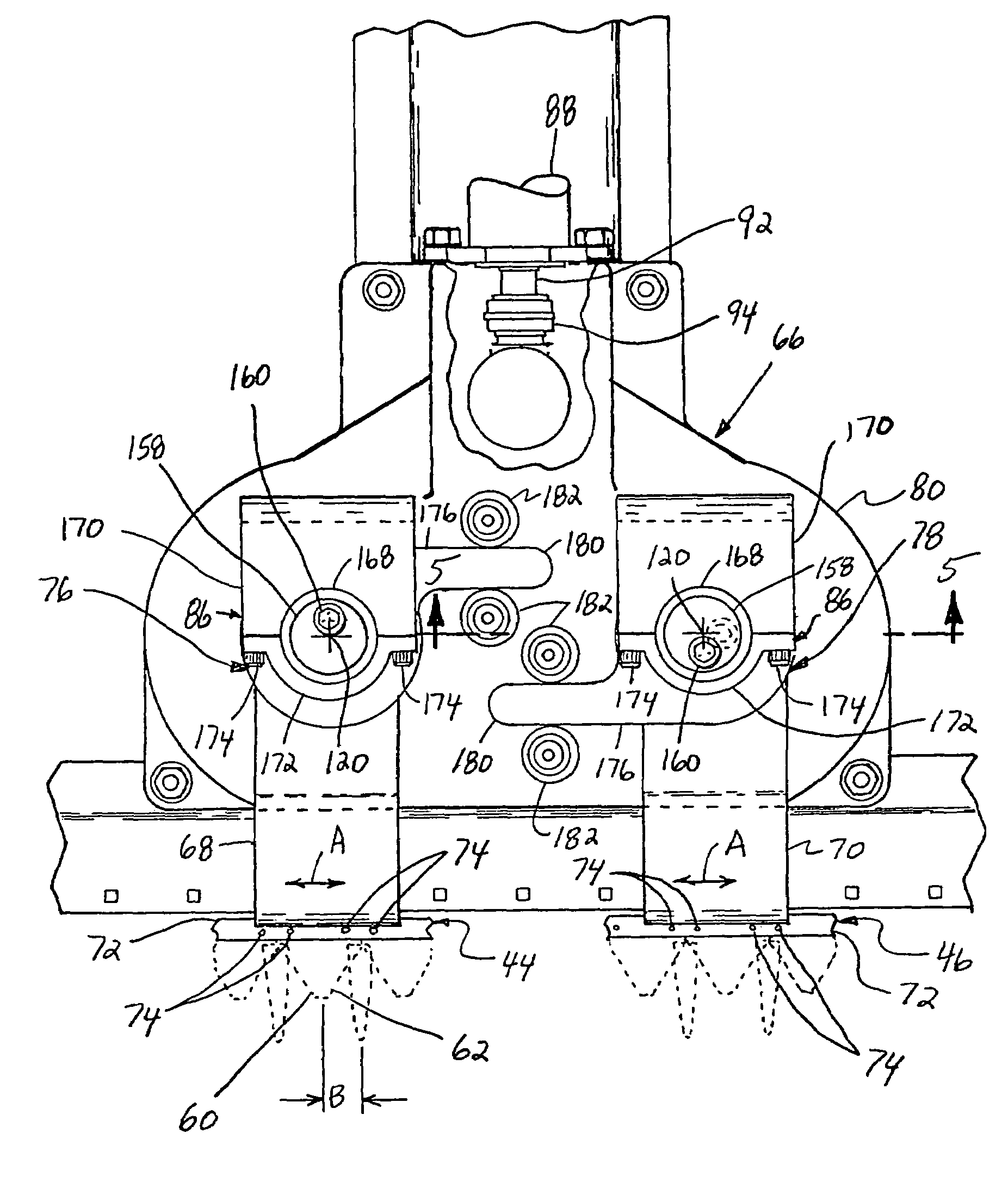
[0043]Referring also to FIGS. 2 and 3, header 22 includes a pan or floor 28 which is supported in desired proximity to the surface of the field during the harvesting operation, and an elongate, sidewardly extending sickle 30 along a forward edge portion 32 of floor 28, sickle 30 being operable for severing the crop for induction into header 22, as will be explained. Header 22...


PUM


Abstract

The compact sickle drive mechanism is adapted to incorporated into or beneath a floor or pan of a header at a location between and spaced from the sides or ends of the header, and can be configured for reciprocatingly driving two knife assemblies disposed in end to end relation, in opposite directions, such that potentially vibratory forces, including those generated by the moving masses of the knife assemblies, at least substantially cancel one another and thus are not transferred to structure of the header. As a result, the overall width of the header and structure thereof can also be reduced.

Description

TECHNICAL FIELD[0001]This invention relates generally to a drive for the sickle of a header of an agricultural cutting machine, such as a combine, windrower or other crop harvesting machine, or a mower, and more particularly, to a compact drive mechanism adapted to be integrated or incorporated into or beneath a floor or pan of a header, particularly at a location between and spaced from the sides or ends of the header, and which can be configured for reciprocatingly driving two knife assemblies of a cutter bar assembly of the sickle disposed in end to end relation, in opposite directions, such that potentially vibratory forces, including those generated by the moving masses of the knife assemblies, at least substantially cancel one another and are not transferred to structure of the header.BACKGROUND ART[0002]Sickles typically including cutter bars supporting a row of knives, have been used to cut plants, including, but not limited to, hay, grasses, small grains and the like, for m...

Claims


Application Information

Patent Timeline
Patent Type & Authority Patents(United States)
IPC IPC(8): A01D34/13
CPCA01D34/145A01D41/142A01D34/30
Inventor PRIEPKE, EDWARD H
Owner BLUE LEAF I P INC
Why Eureka
Try Eureka