Canopy chair

a chair and canopies technology, applied in the field of canopies, can solve the problems of other limitations of the related art, and achieve the effect of reducing the number of chairs and reducing the number of insects

Active Publication Date: 2008-10-07
SPIN MASTER INC
View PDF85 Cites 57 Cited by
  • Summary
  • Abstract
  • Description
  • Claims
  • Application Information

AI Technical Summary

Problems solved by technology

Other limitations of the related art will become apparent to those of skill in the art upon a reading of the specification and a study of the drawings.

Method used


Image

  • Canopy chair
  • Canopy chair
  • Canopy chair

Examples


Embodiment Construction

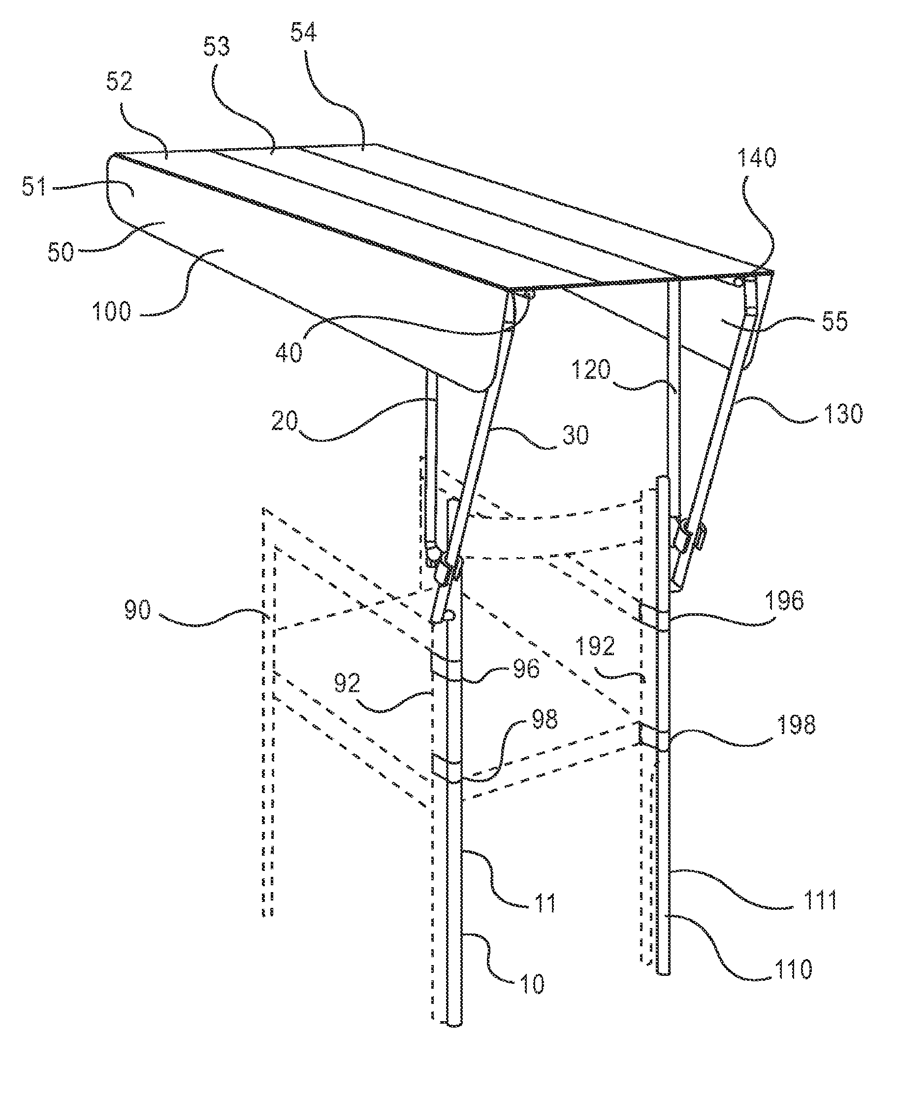
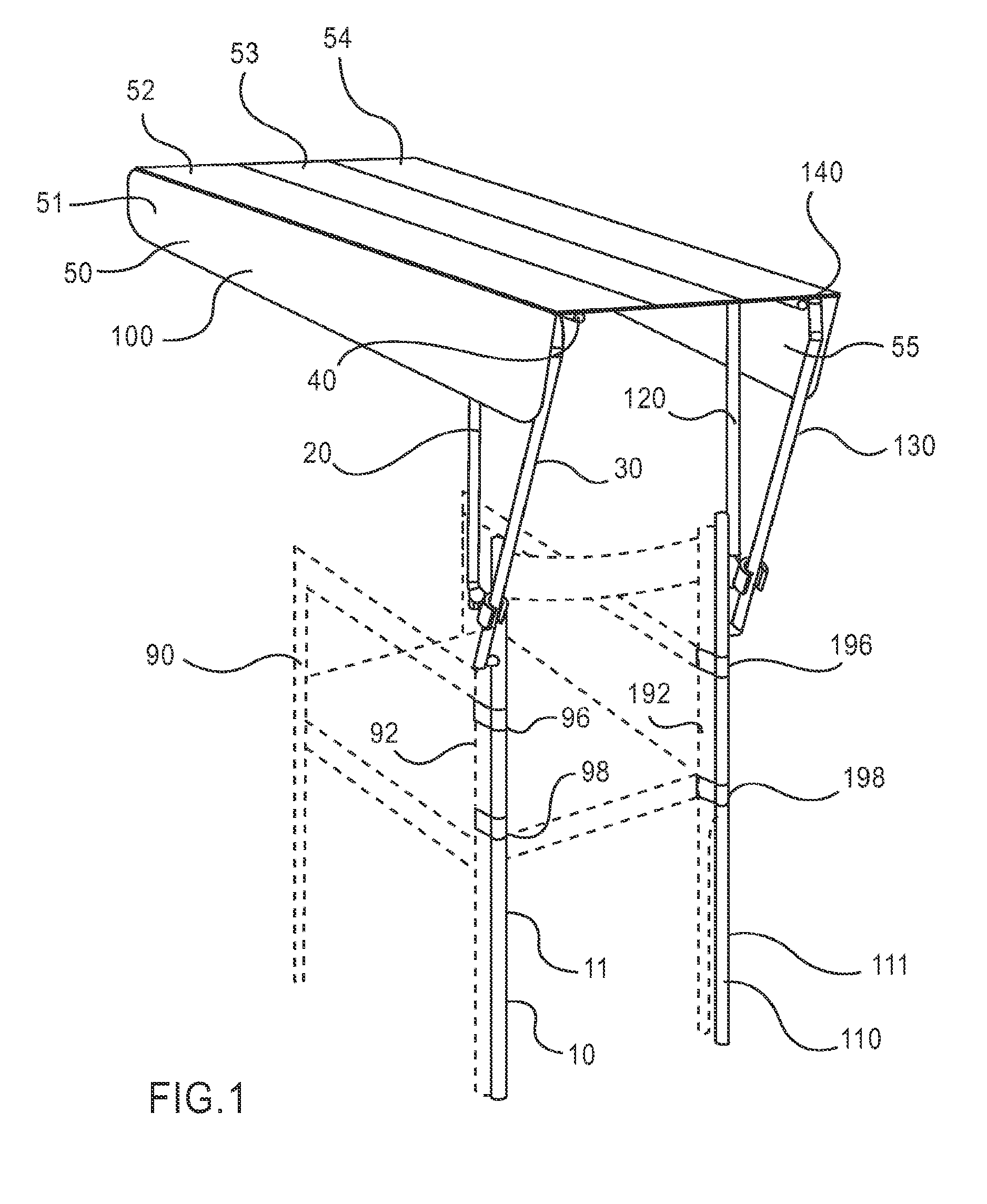
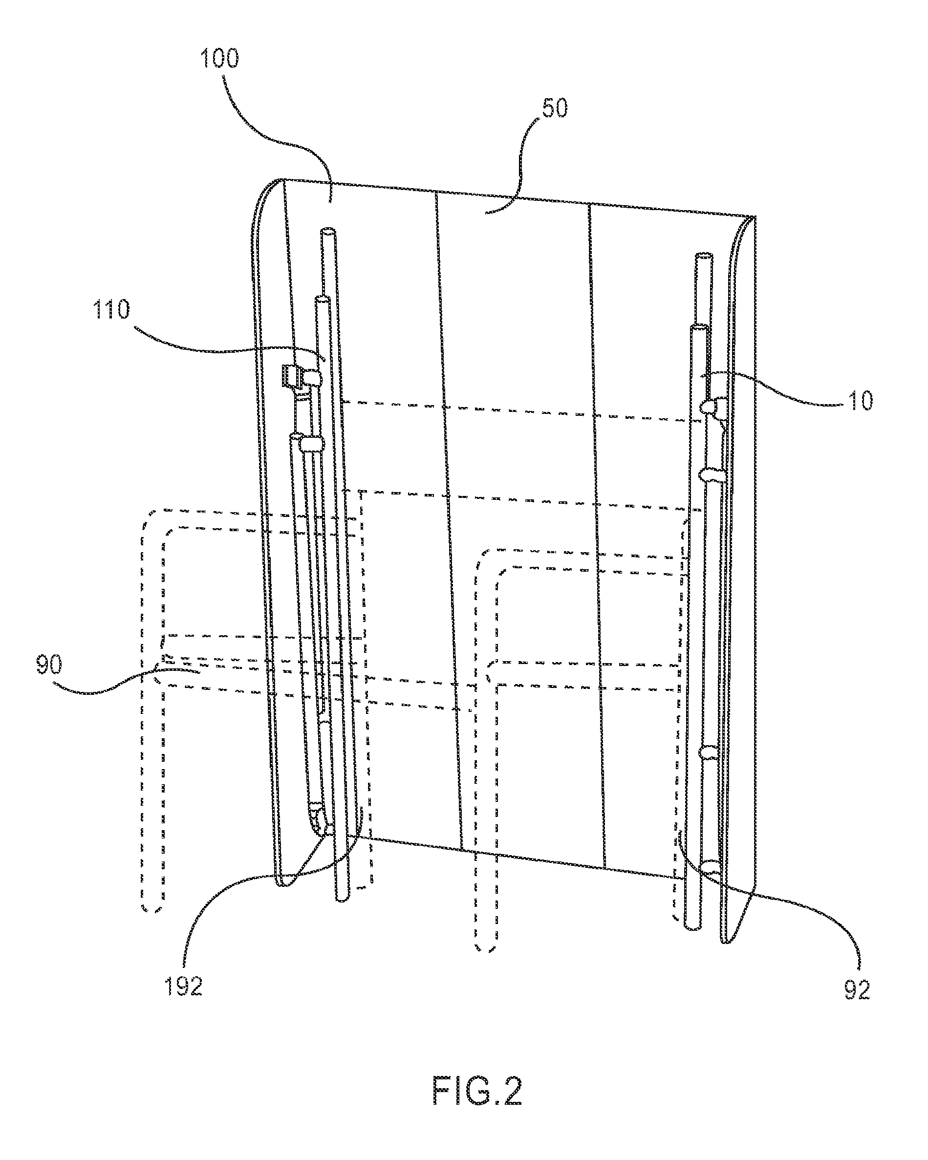
[0043]FIG. 1 is a perspective view of an embodiment canopy attached to a chair in the overhead position. Any suitable conventional folding chair may be used in this embodiment. The chair 90 is depicted in dashed lines in FIG. 1. The left vertical chair back 92 and right vertical chair back 192 are depicted. The embodiment canopy 100 shown in FIG. 1 is comprised of a canopy 50 which is supported by a left frame 10 and by a right frame 10. The left vertical support 11 element of the left frame 10 is attached by upper 96 and lower 98 connectors to the left vertical chair back 92. The right vertical support 110 element of the right frame 110 is attached by upper 196 and lower 198 connectors to the left vertical chair back 92. Other components of the left frame 10 visible in FIG. 1 are the left forward bar 20, left rear bar 30, and the left support arm 40, which supports the canopy 50. Other components of the right frame 110 visible in FIG. 1 are the right forward bar 120, right rear bar...


PUM


Abstract

An exemplary embodiment providing one or more improvements includes a frame which attaches to outdoor furniture, in particular to a chair, and a canopy. Embodiments can be moved from an overhead position to a behind the chair position. The frames can be moved form a collapsed to a fully extended position. In embodiments the canopy can be positioned to contain the collapsed frame and chair in the carrying position.

Description

CROSS-REFERENCE(S)[0001]This application claims priority from provisional patent application Ser. No. 60 / 701,905, filed Jul. 22, 2005.STATEMENT REGARDING FEDERALLY SPONSORED RESEARCH OR DEVELOPMENT[0002]Not Applicable.REFERENCE TO A “MICROFICHE APPENDIX”[0003]Not Applicable.BACKGROUNDDescription of Related Art Icluding Information Disclosed Under 37 CFR 1.97 AND 37 CFR 1.98[0004]U.S. Pat. No. 4,295,481 discloses an adjustable sunshade with a fabric covered canopy constructed out of a plastic such a polypropylene or out of metal such as aluminum or out of wood.[0005]U.S. Pat. No. 4,635,667 discloses a canopy which is slid ably attached to the back of a chair and which may be adjusted using a tension cap.[0006]U.S. Pat. No. 4,687,249 discloses an adjustable canopy for a beach chair in which the fabric canopy is attached to a frame by side members which project from tubular side members on the back of the chair.[0007]U.S. Pat. No. 4,924,896 discloses a fabric covered collapsible canopy...

Claims


Application Information

Patent Timeline
Patent Type & Authority Patents(United States)
IPC IPC(8): A47C7/66A47C4/00A47C4/28
CPCA47C7/66A47C4/00A47C1/0265
Inventor REEB, DAVIDROBINETTE, PAUL
Owner SPIN MASTER INC
Why Eureka
Try Eureka