Cab receptacle with indicator light

a technology for cab receptacles and indicator lights, which is applied in emergency power supply arrangements, coupling device connections, instruments, etc., and can solve problems such as unfavorable vehicle operators, power sources located at truck stops, rest stations or vehicle service stations that do not always function properly, and unfavorable vehicle operators

a technology for cab receptacles and indicator lights, which is applied in emergency power supply arrangements, coupling device connections, instruments, etc., and can solve problems such as unfavorable vehicle operators, power sources located at truck stops, rest stations or vehicle service stations that do not always function properly, and unfavorable vehicle operators

US7439851B2Active Publication Date: 2008-10-21PHILLIPS & TEMRO INDS

Image

  • Cab receptacle with indicator light
  • Cab receptacle with indicator light
  • Cab receptacle with indicator light

Examples


Embodiment Construction

[0020]The following description of the preferred embodiment(s) is merely exemplary in nature and is in no way intended to limit the invention, its application, or uses.

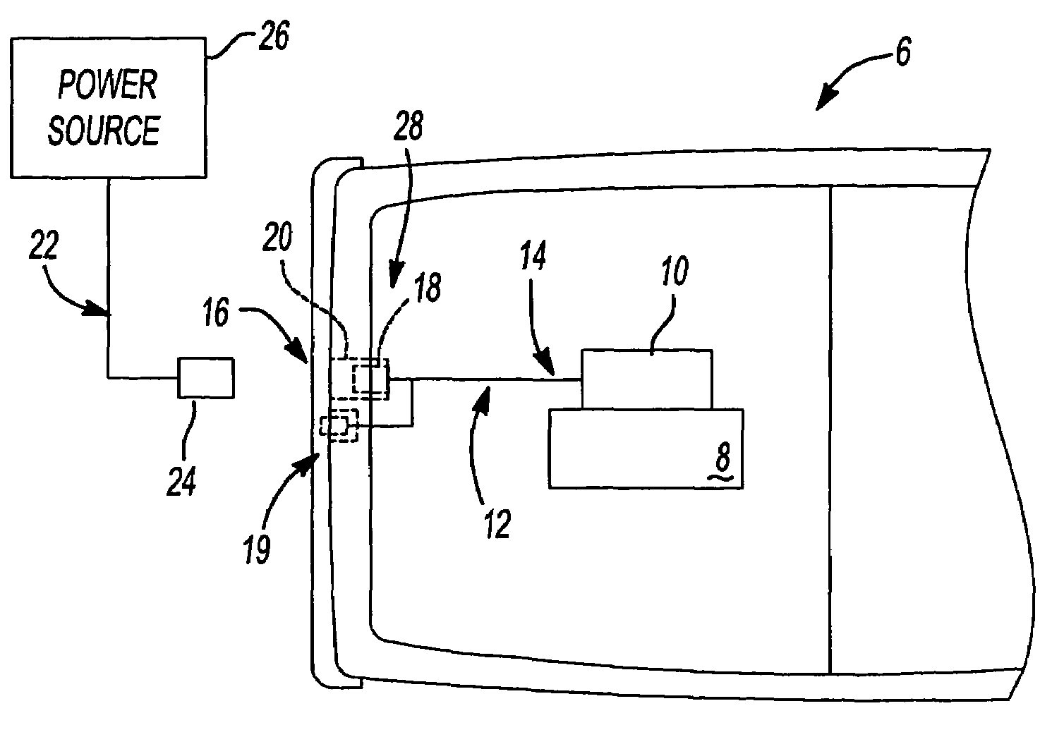
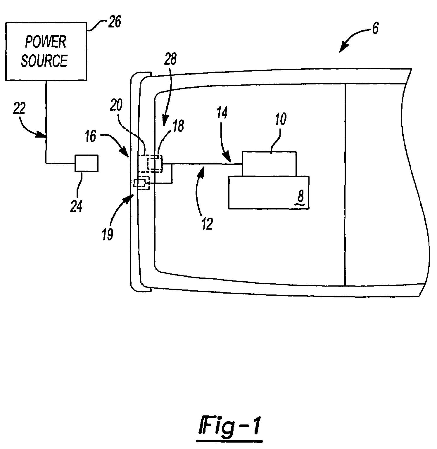
[0021]FIG. 1 depicts a vehicle 6 including an engine 8 and a powered automobile accessory 10, such as an engine block heater. A cord set 12 has a first end 14 electrically connected to the accessory 10 and a second bifurcated end 16. One portion of bifurcated end 16 terminates at a plug 18. The other end terminates at an indicator 19. Plug 18 is coupled to a receptacle 20 that is mounted to the vehicle 6. An auxiliary cord 22 includes a plug 24 for selectively interconnecting cord set 12 to a power source 26 via plug 18. The power source 26 includes an alternating current electrical outlet such as those generally mounted in the walls of building structures.

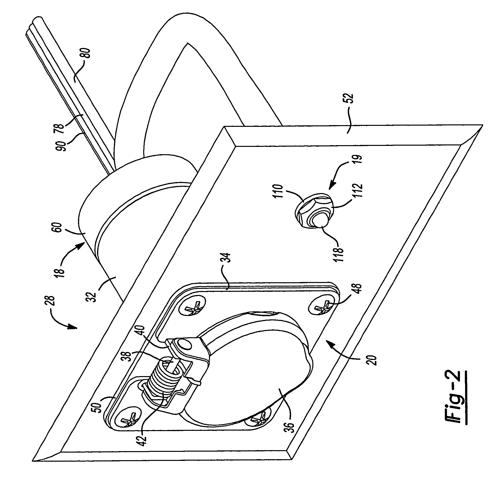
[0022]FIGS. 2-5 depict an electrical indicator system 28 including receptacle 20 and cord set 12 equipped with plug 18 and indicator 19. Receptacle 20 includes a su...


PUM


Abstract

An electrical indicator system and a method for operating the system includes a plug adapted to be electrically coupled to a power source remote from the vehicle and an indicator adapted to be mounted to the vehicle at a visible location. The indicator is operable to provide a first visual indication when electrical power is present at the plug. The indicator provides a second visual indication, different from the first visual indication, when current is flowing through the plug.

Description

BACKGROUND AND SUMMARY OF THE INVENTION[0001]The present invention relates generally to electrically powered accessories for motor vehicles and, more particularly, to an electrical indicator system for motor vehicles.[0002]Various electrically powered devices are designed for use with vehicles including automobiles, light-duty trucks and heavy-duty vehicles. These devices, including cold weather starting devices such as radiant heaters, engine block heaters, fluid heaters, battery warmers, and the like, are generally fixed to the automobile and operationally connected to an-appropriate component of the vehicle engine. The operation of these devices generally occurs upon connection to a power source external to the vehicle. As such, a factor in the sales and use of these devices is the simplicity with which the device can be electrically connected to the power source. To address this concern, cord sets have been developed that include a receptacle connected to the vehicle body for mo...

Claims


Application Information

Patent Timeline
21 Oct 2008
Publication
US7439851B2
IPC
B60Q1/00; G08B21/00
CPC
B60D1/60; B60D1/64
Inventors
FLEURY, PHILIP J.; ZUBIN, CLAUDIO