Transmitter for surveillance camera, and surveillance system

a technology for transmitting devices and surveillance cameras, applied in television systems, frequency-division multiplexes, instruments, etc., can solve the problems of intrinsically limited life of storage batteries, practically non-negotiable expenses of transmission techniques, etc., and achieve the effect of enhancing security functionality and simplifying wiring work

Inactive Publication Date: 2005-09-06
MURAKAMI CORP
View PDF8 Cites 8 Cited by
  • Summary
  • Abstract
  • Description
  • Claims
  • Application Information

AI Technical Summary

Benefits of technology

[0023]Fabrication and use of such a video signal superposing/power deriving unit enables the utilization of the antenna lead-in wire as a signal transmission line and a power code, serving to simplify the wiring work.
[0024]In every aspect of the

Problems solved by technology

Accordingly, necessary wiring of a power cord and a video signal transmission line produces a burdensome wiring task, and rather finding room for the wiring is necessitated.
However, the aforementioned radio transmission techniques with a solar and storage b

Method used


Image

  • Transmitter for surveillance camera, and surveillance system
  • Transmitter for surveillance camera, and surveillance system
  • Transmitter for surveillance camera, and surveillance system

Examples


Embodiment Construction

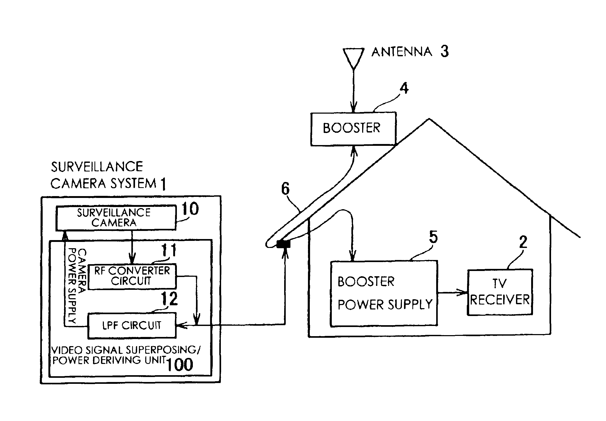
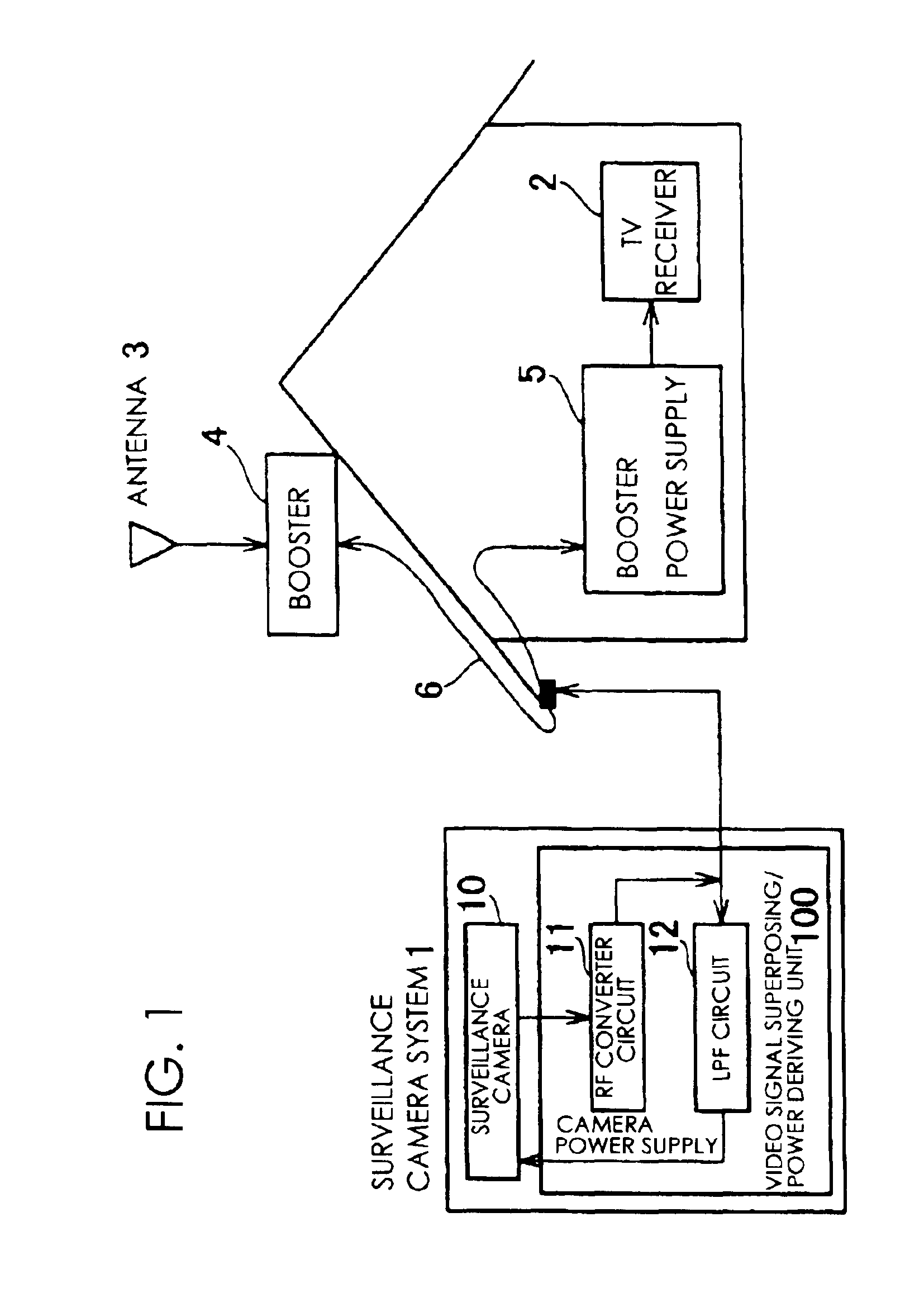
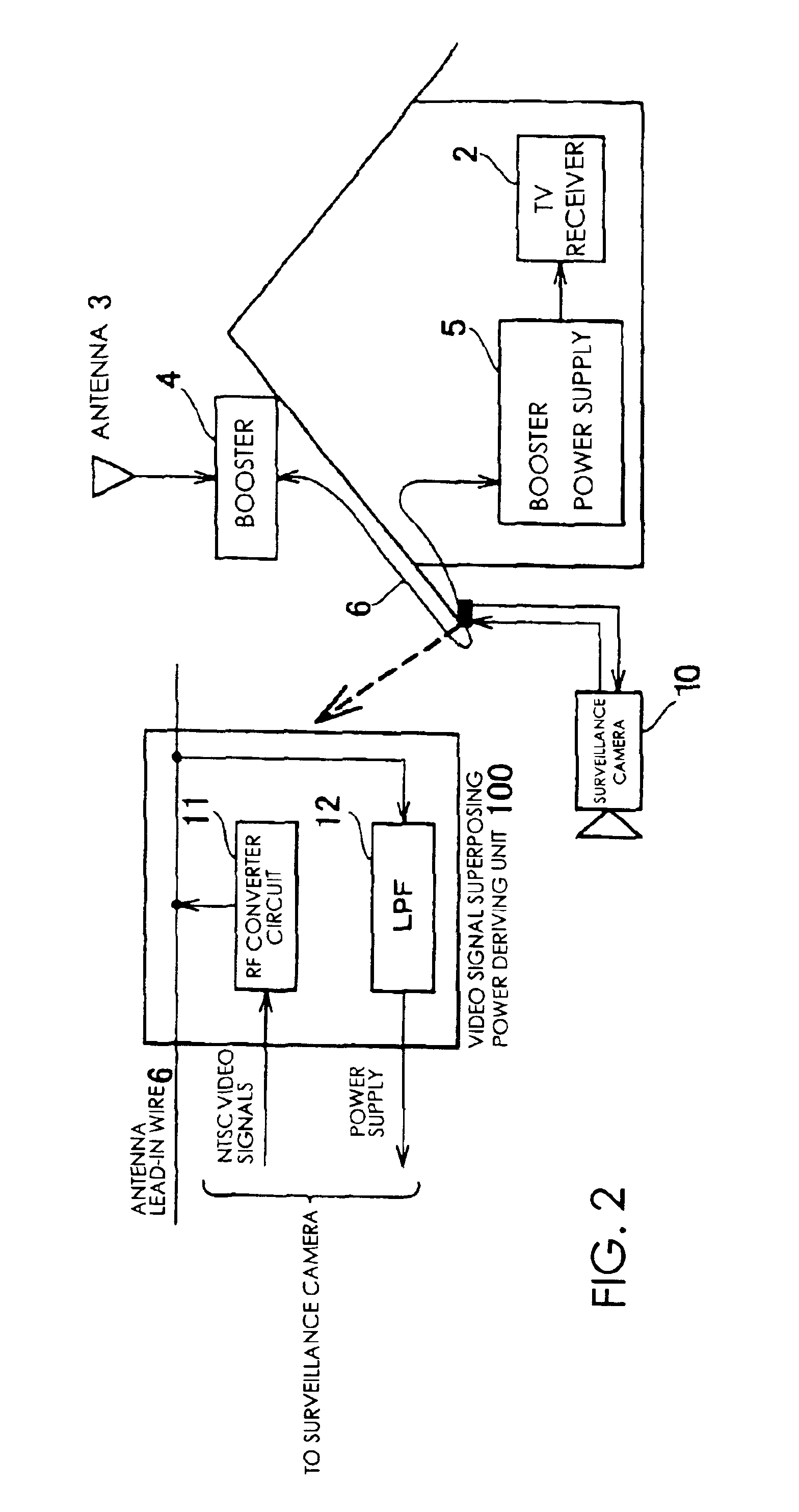
[0046]A description will be given of one exemplified embodiment of a transmitter for a surveillance camera system according to the present invention with reference to FIG. 1.

[0047]In FIG. 1, denoted by 1 is a surveillance camera system, and denoted by 2 is a television receiver (TV set) in common use in ordinary households. In the ordinary households, for the purpose of watching TV, an antenna 3 is provided to receive signals broadcast over airwaves, which are amplified by a booster 4 installed outdoors, led into the house and distributed to the television receiver 2. A booster power supply 5 is provided between the booster 4 and the television receiver 2, and serves to supply the booster 4 with power (direct current) through an extra channel superposed in a coaxial cable 6 that is normally provided as an antenna lead-in wire.

[0048]The surveillance camera system 1 includes a surveillance camera 10 and a video signal superposing / power deriving unit (circuit) 100.

[0049]The video signa...


PUM


Abstract

An RF converter circuit 11 that constitutes a video signal superposing/power deriving unit 100 converts video signals generated from images taken by a surveillance camera 10, which derives a direct current voltage as a driving power from an antenna lead-in wire 6 through a filter circuit (LPF circuit 12), to radio-frequency signals. The radio-frequency signals are transmitted through the antenna lead-in wire 6 to a television receiver 2. Images taken by the surveillance camera 1 can be viewed on the television receiver 2 only by selecting the channel assigned to the surveillance camera 1. Accordingly, the driving power for the surveillance camera 1 is not relied upon a solar battery or secondary batteries, and wiring work therefor may be simplified.

Description

BACKGROUND OF THE INVENTION[0001]This invention relates to a transmitter for a surveillance camera, and a surveillance system, and more particularly to a transmitter for transmitting images taken by a surveillance camera to a television receiver.[0002]Among prevailing transmitters for transmitting images taken by a surveillance camera to a television receiver are, typically, those which come with door camera systems and video door phone systems. Each of these systems employs a surveillance camera provided at a front door or the like for security purposes, and commonly includes a wired means of communication through which images taken by the surveillance camera are transmitted to the receiver and displayed on a monitor thereof. Accordingly, necessary wiring of a power cord and a video signal transmission line produces a burdensome wiring task, and rather finding room for the wiring is necessitated.[0003]On the other hand, radio transmission techniques are disclosed, for example, in J...

Claims


Application Information

Patent Timeline
IPC IPC(8): G08B1/00G08B1/08H01P5/00H04Q7/00H04N7/18
CPCH04N7/18
Inventor NAGAO, MITSUYOSHISATO, HIDENORI
Owner MURAKAMI CORP
Why Eureka
Try Eureka