
Power generating and propelling system of vessel

a technology of power generation and propelling system, which is applied in the direction of vessel auxillary drive, vessel construction, electric generator control, etc., can solve the problems of insufficient supply of electric power output from the battery 106/b> charged by the alternator 105/b> to all inboard electric equipment, and achieve the prevention of vertical drop water, the strengthening of the generating device casing, and the effect of enhancing cooling efficiency

Inactive Publication Date: 2005-12-29
YANMAR CO LTD
View PDF6 Cites 0 Cited by
  • Summary
  • Abstract
  • Description
  • Claims
  • Application Information

AI Technical Summary

Benefits of technology

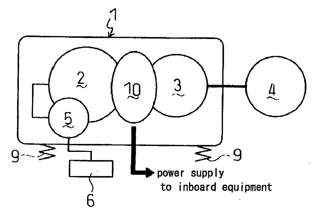
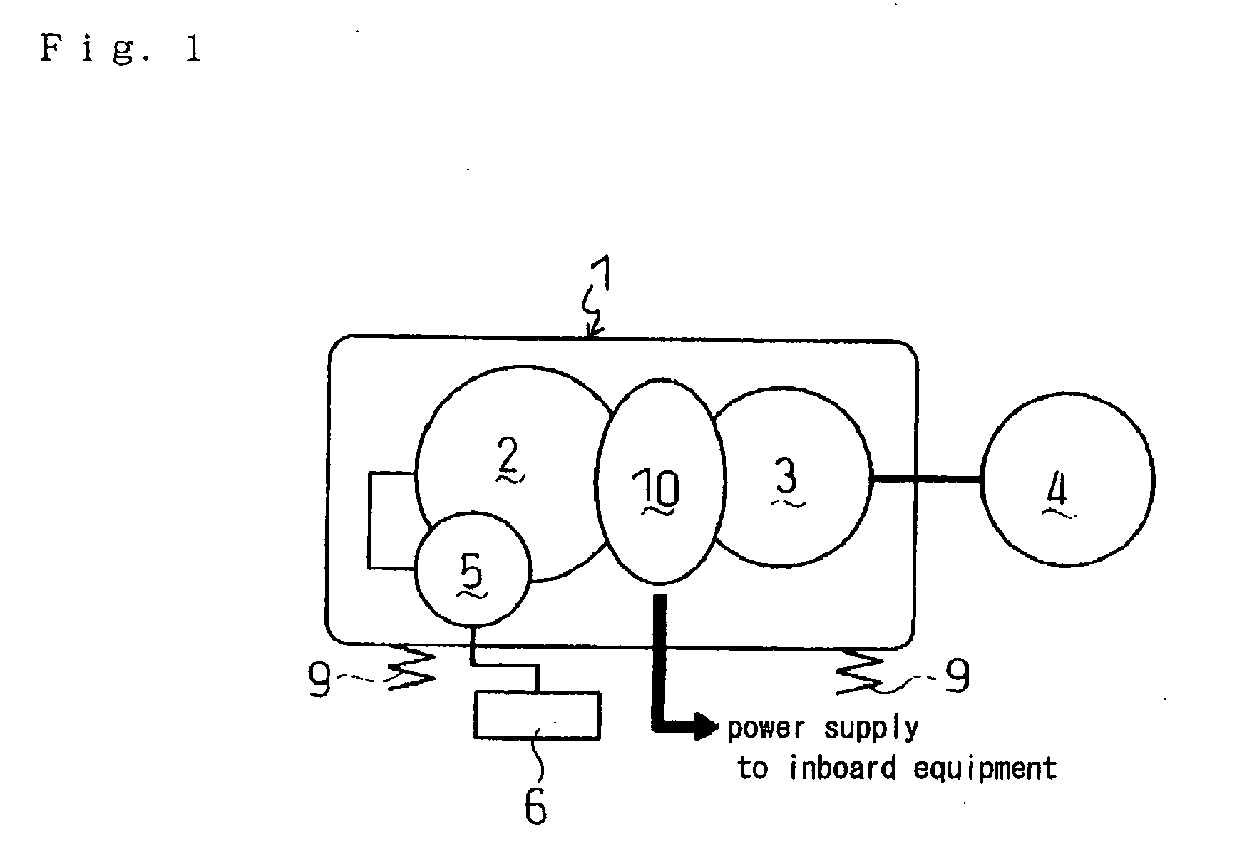
[0017] According to the present invention, a power generating and propelling system of a vessel in which an electric power generating device is disposed between an internal combustion engine and a transmission. While a stator of the generating device is disposed in either a flywheel housing of the internal combustion engine or a casing connected to the flywheel housing, a rotary shaft of the generating device is disposed in the same direction with a crankshaft of the internal combustion engine or a rotary shaft of the transmission. The electric power generating device can be used as either a motor or a generator. Therefore, a count of shafts for transmitting the driving force from the internal combustion engine to the transmission can be reduced so as to simplify a structure for transmitting it.
[0018] Furthermore, according to the present invention, the rotary shaft of the electric power generating device is disposed coaxially to a crankshaft of the internal combustion engine or any rotary shaft of the transmission. Therefore, the count of shafts for transmitting the driving force from the internal combustion engine to the transmission can be reduced, and the whole propelling machine can be balanced in weight so as to reduce its vibration. Electric power generated by the generating device is larger than that by the conventional alternator so that inboard equipments on the vessel can be supplied with sufficient electric power, while keeping the vessel-propelling machine compact so as to save a space. Additionally, the compacted propelling machine can be easily mounted onto the vessel body. The electric power generating device may be supplied with electric power from a battery or another so as to serve as a motor, which can be used as an engine-starting motor or as a power supply in combination with the internal combustion engine. The common generating device can be still used even when the specification of the transmission connected to the internal combustion engine is changed, whereby the generating device is accommodated to various transmissions so as to enhance the flexibility of the generating device. In comparison with the case that the generating device is exposed, the generating device built in the flywheel housing or a casing connected to the flywheel housing can be protected so as to reduce troubles and to enhance reliability. When the generating device is directly built in the flywheel housing, the propelling machine can be shortened in the direction of the crankshaft, thereby being compacted.
[0019] Alternatively, according to the present invention, the rotary shaft of the generating device is disposed eccentrically and parallel to the crankshaft of the internal combustion engine or any rotary shaft of the transmission. Therefore, a plurality of generating units can be disposed in the generating device, and the count of the generating units to be disposed may be arbitrarily determined so as to set suitable scale of output power generated by the generating. For driving the rotary shaft of the generating device by the crankshaft of the internal combustion engine or the rotary shaft of the transmission, a drive gear fixed on the crankshaft of the internal combustion engine or the rotary shaft of the transmission meshes with a driven gear fixed on the rotor shaft of the generating device. The gear ratio between the meshing drive and driven gears may be arbitrarily changed so as to change the scale of generated electric output power. Therefore, the adaptability of internal combustion engines having difference specifications to be connected to the transmission can be enhanced.

Problems solved by technology

However, electric power outputted from the battery 106 charged by the alternator 105 is insufficient to be supplied to all inboard electric equipments.
However, this construction expands the whole of vessel-propelling machine 101 so as to require a considerably large installation space.

Method used


Image

  • Power generating and propelling system of vessel
  • Power generating and propelling system of vessel
  • Power generating and propelling system of vessel

Examples


first embodiment

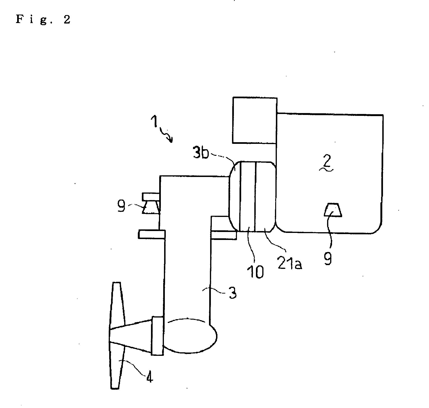
[0190] A sail-drive propelling machine 201 will now be described.

[0191] As shown in FIGS. 21 and 22, a flywheel 221 is disposed on one end of a crankshaft 202a of the internal combustion engine 202 so as to be rotated by the crankshaft 202a serving as an output shaft of the engine 202. The flywheel 221 is covered with a flywheel housing (hereinafter referred to as “FW housing”) 221a.

[0192] A generating device casing 240 is attached to the rear portion of the FW housing 221a. Members constituting the generating device 210 are built in the generating device casing 240. Specifically, stator coils 218 are attached onto the inner peripheral surface of the generating device casing 240 and a magnet 212 is arranged radially inward of the stator coils 218 (toward the center). The magnet 212 is fixed to a distance piece 224, which is a rotary member, through a cylindrical attachment member 219. The magnet 212, the attachment member 219, and a flange part 224b of the distance piece 224 funct...

second embodiment

[0300] Next, a sail-drive propelling machine 201 will be described.

[0301] In the propelling machine 201 of the second embodiment as shown in FIGS. 48 and 49, a generating device casing 250 equals the generating device casing 240 of the first embodiment united with FW housing 221a and mounting flange 203b.

[0302] Besides, the configuration of the propelling machine 201 according to the second embodiment, e.g., the form of cooling fans 236, 237 and 238, is substantially similar to that of the propelling machine 201 according to the first embodiment. A reshaped electric power generating device shown in FIG. 70 used in this embodiment is constructed substantially similar to the reshaped generating device used in the propelling machine 201 of the first embodiment.

[0303] The generating device casing 250 used in the propelling machine 201 of the second embodiment will be described.

[0304] The generating device casing 250 has a front flange part 257a which projects outward from the front ...

third embodiment

[0325] Next, the sail-drive propelling machine 201 will be described.

[0326] In the propelling machine 201 of the third embodiment as shown in FIGS. 56 and 57, a generating device casing 260 equals the generating device casing 240 of the first embodiment united with the FW housing 221a.

[0327] Besides, the configuration of the propelling machine 201 according to the third embodiment, e.g., the form of cooling fans 236, 237 and 238, is substantially similar to that of the propelling machine 201 according to the first embodiment. A reshaped electric power generating device shown in FIG. 58 used in this embodiment is constructed substantially similar to the reshaped generating device used in the propelling machine 201 of the first embodiment.

[0328] The generating device casing 260 used in the propelling machine 201 of the third embodiment will now be described.

[0329] A front flange part 267a projects outward from the front portion of the generating device casing 260 to serve as a par...


PUM


Abstract

A power generating and propelling system of a vessel has an electric power generating device (10) installed between an internal combustion engine (2) and a transmission (3). A stator (11) of the generating device (10) is built in a flywheel housing (21a) of the internal combustion engine (2) or a casing (10a) connected to the flywheel housing (21a). A rotary shaft of the generating device (10) is disposed coaxially or eccentrically parallel to a crankshaft (2a) of the internal combustion engine (2) or an input shaft (3a) of the transmission (3) in the same direction with the crankshaft (2a) of the internal combustion engine (2).

Description

CROSS REFERENCE TO RELATED APPLICATIONS [0001] This application is a Continuation of U.S. application Ser. No. 10 / 787,956 filed Feb. 27, 2004, which is a Continuation-in-part of PCT / JP02 / 08713 filed Sep. 11, 2001.BACKGROUND OF THE INVENTION [0002] 1. Field of the Invention [0003] The present invention relates to the construction of a vessel-propelling machine having an internal combustion engine for propelling a vessel and a power generating device for supplying electric power to inboard equipments. [0004] 2. Background Art [0005] A conventional vessel-propelling machine comprises an internal combustion engine, a transmission and others, wherein a propeller connected to the transmission is driven by the driving force of the internal combustion engine decelerated through the transmission. [0006] Moreover, conventionally, a battery stores electric power to be supplied to inboard electric equipments, and a power generator such as an alternator is attached to the internal combustion eng...

Claims


Application Information

Patent Timeline
Patent Type & Authority Applications(United States)
IPC IPC(8): B63H21/38B60L50/10B63J3/02B63J99/00F01P3/20F02B63/04F02B77/00F02D29/06H02K7/18H02P9/06
CPCB63B2770/00H02K7/1815B63J3/02B63H23/24B63J2003/002
Inventor MORI, HISANORINAKAGAKI, MITSUHIROYUKINO, HIROYASUTODA, TAKAYUKIHITACHI, JUNICHIIMANAKA, TOSHIO
Owner YANMAR CO LTD
Learn More