Distributed optical fiber temperature measuring system

A distributed optical fiber and optical device technology, applied in thermometers, measuring devices, measuring heat, etc., can solve the problems that reflected light cannot correctly reflect the temperature field, improve detection sensitivity, and increase measurement time, so as to reduce the cost of temperature measurement and reduce The number of devices and the effect of improving accuracy

Active Publication Date: 2014-03-19
SHANGHAI BAIANTEK SENSING TECH CO LTD
View PDF5 Cites 7 Cited by
  • Summary
  • Abstract
  • Description
  • Claims
  • Application Information

AI Technical Summary

Problems solved by technology

[0004] At this point, if the incident light power of the pulsed light source continues to increase, due to the limitation of physical characteristics, it will cause stimulated scattering of light in the fiber, resulting in the generation of nonlinear effects, and the reflected light at this time cannot correctly reflect its temperature. field information
The more software averages, the longer it takes. Theoretical calculations show that under a certain signal-to-noise ratio, software averaging cannot improve the temperature demodulation accuracy without limit, but it also needs to increase a lot of measurement time.
However, due to the limitation of materials, the detection sensitivity of avalanche diodes cannot be improved without limit.
Therefore, when the demand for long-distance detection arises, traditional products are powerless

Method used


Image

  • Distributed optical fiber temperature measuring system
  • Distributed optical fiber temperature measuring system

Examples


Embodiment Construction

[0025] In order to understand the technical content of the present invention more clearly, the following examples are given in detail.

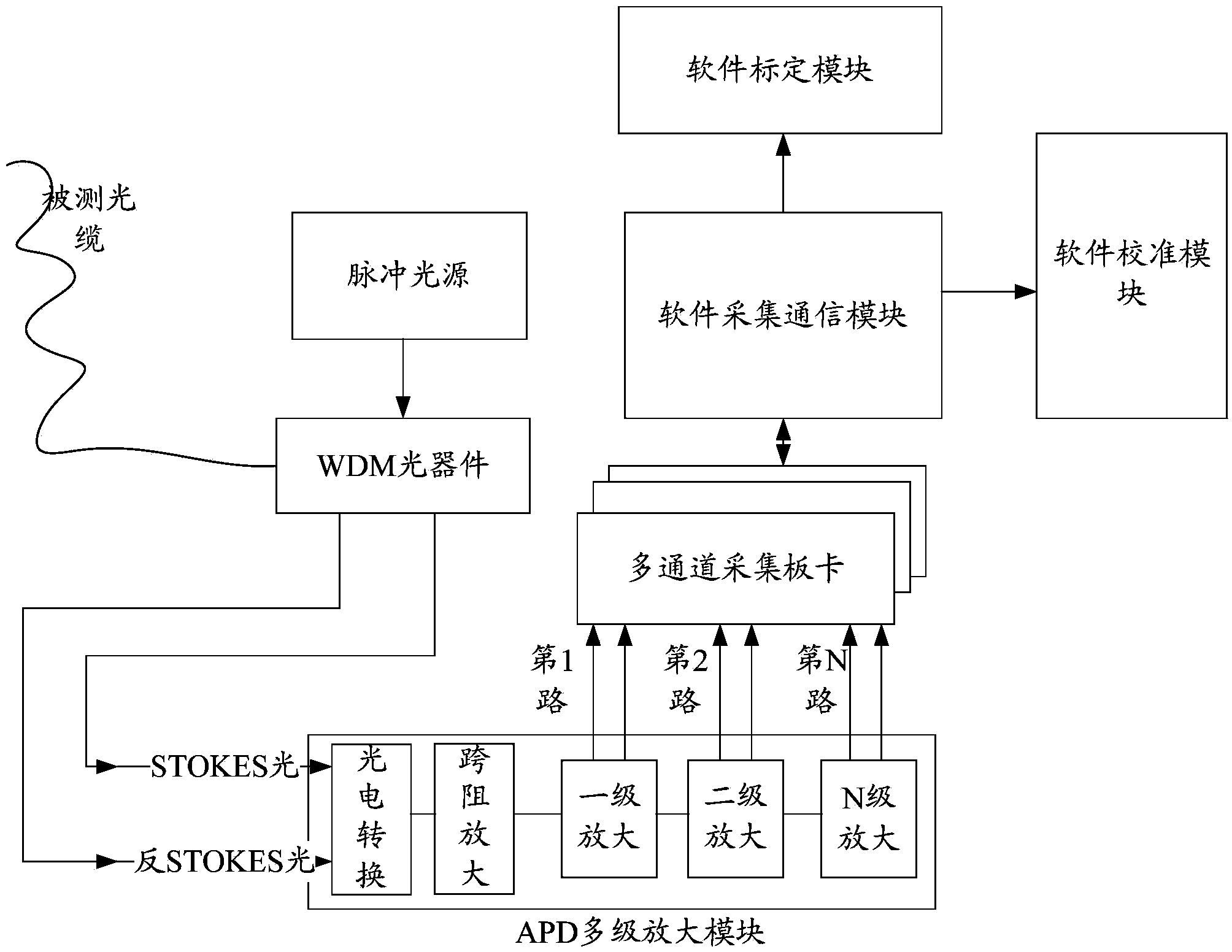
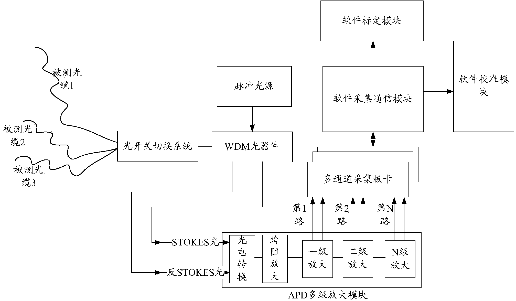
[0026] see figure 1 , the distributed optical fiber temperature measurement system, including WDM optical devices (WDM is the abbreviation of Wavelength Division Multiplexing, translated as wavelength division multiplexing) and APD multi-stage amplification module (Avalanche Photo Diode, that is, avalanche photodiode), the measured optical cable is connected For the WDM optical device, the output end of the pulse light source is connected to the WDM optical device, and the APD multi-stage amplification module is used to receive the optical signal sent by the WDM optical device, and output the analog signal to the multi-channel acquisition board in segments. The board is connected with the software platform, and the software platform is used to receive the analog signal sent by the multi-channel acquisition board, and synthesize one signal aft...


PUM


Abstract

The invention relates to a distributed optical fiber temperature measuring system which comprises a wavelength division multiplexing (WDM) optical device and an APD multistage amplifying module. A measured optical cable is connected with the WDM optical device, the output end of a pulse light source is connected with the WDM device, and the APD multistage amplifying module is used for receiving optical signals transmitted by the WDM optical device and outputting simulation signals to a multi-channel collection board card in a segmentation mode. The multi-channel collection board card is connected with a software platform, and the software platform is used for receiving the simulation signals transmitted by the multi-channel collection board card, conducting segmentation processing on the signals and combining the signals into a whole channel. The distributed optical fiber temperature measuring system with the structure effectively extends optical fiber measuring distance of a single channel, the device number is reduced, problems of signal transmission, device power supply, device maintenance and the like caused by device cascade connection required by long-distance transmission measurement are solved, product measuring distance is increased, temperature measuring cost is reduced, temperature measuring accuracy is improved, the signal to noise ratio of measuring signals of each segment is kept at a high level, and the temperature measuring accuracy is improved.

Description

technical field [0001] The invention relates to an optical fiber temperature measuring device, in particular to a long-distance and high-precision distributed optical fiber temperature measuring system including a multi-stage amplification detection circuit. Background technique [0002] The distributed optical fiber temperature measurement system based on Raman scattering or Brillouin scattering is a system designed according to the temperature effect of optical time domain reflection of optical fiber and spontaneous scattering of optical fiber. It is mainly used to detect the temperature of different positions along the optical fiber in real time and realize Continuous temperature measurement of the entire temperature field. In the distributed optical fiber temperature measurement system, the optical fiber is both the transmission medium and the sensing medium. It also has the advantages of anti-electromagnetic interference, flame-proof, small size, and small impact on the...

Claims


Application Information

Patent Timeline
Patent Type & Authority Applications(China)
IPC IPC(8): G01K11/32G01K11/324
Inventor 陈兵
Owner SHANGHAI BAIANTEK SENSING TECH CO LTD
Why Eureka
Try Eureka