Infrared medium-long wave double wave band imaging optical system

An imaging optics, medium and long-wave technology, applied in the field of infrared optical systems, can solve the problems of increasing the difficulty of the optical system, and achieve the effects of increased detection distance, high transmittance, and low cost

Inactive Publication Date: 2011-09-28
SHANGHAI INST OF TECHNICAL PHYSICS - CHINESE ACAD OF SCI
View PDF4 Cites 17 Cited by
  • Summary
  • Abstract
  • Description
  • Claims
  • Application Information

AI Technical Summary

Problems solved by technology

These properties make it more difficult for the optical system

Method used


Image

  • Infrared medium-long wave double wave band imaging optical system
  • Infrared medium-long wave double wave band imaging optical system
  • Infrared medium-long wave double wave band imaging optical system

Examples


Embodiment Construction

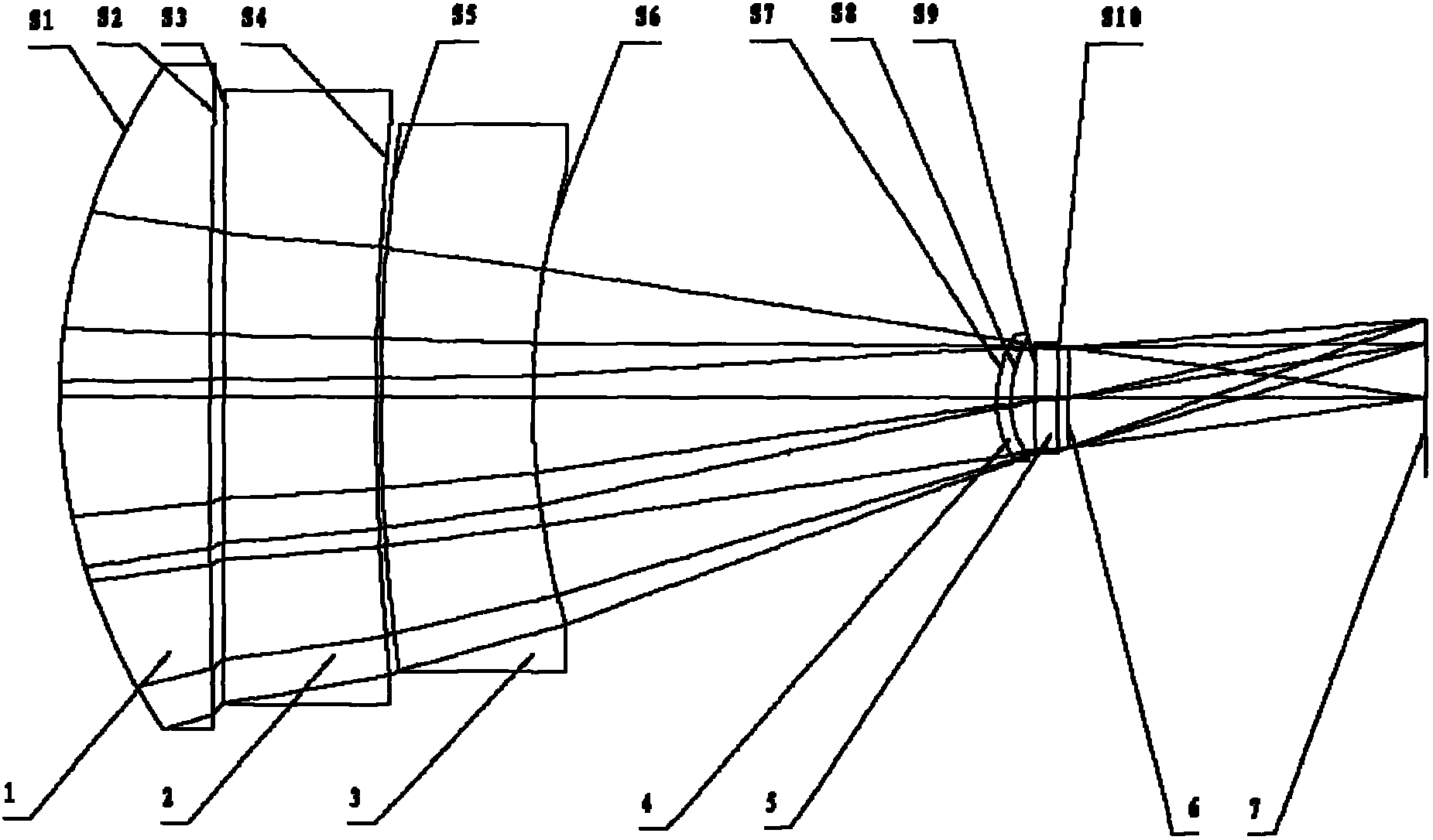
[0012] According to attached figure 1 As shown in the schematic diagram of the present invention, the parameters of the four-piece refraction infrared medium-long-wave dual-band imaging optical system of the present invention are shown in the following table:

[0013] Face number

surface type

Radius of curvature (mm)

Thickness (mm)

Material

Cone factor (k)

Object surface

0

S1

sphere

182.719

33.944

AMTIR1

0

S2

sphere

4302.688

3.11

0

S3

sphere

34

germanium

0

S4

sphere

933.984

1

0

S5

sphere

648.096

34

Zinc sulfide

0

S6

sphere

253.952

104.25

0

S7

Aspherical

38.14

3.104

Zinc sulfide

-0.036

S8

sphere

35.125

5.548

0

S9

flat

5

germanium

0

...


PUM


Abstract

The invention discloses an infrared medium-long wave double wave band imaging optical system which is mainly used for an infrared focal plane imaging system. The invention puts forward a tetra-sheet optical system. A light beam coming from an infinite distance object space in order passes through a first lens, a second lens, a third lens, a fourth lens, a Dewar window and a aperture diaphragm to form an imagining on an image plane. The aperture diaphragm of the system superposes the Dewar cold diaphragm of a refrigeration photoconductor. According to the system, medium-long wave infrared (MWIR, 3 to 5 [mu] m) and long wave infrared (LWIR, 8 to 12 [mu] m) wave bands form imaginings on a same focal plane. In the system, the relative aperture is 1 to 3, the focal length is 300 millimeters and the field of view is 8 degree. The structure of the invention is mainly characterized by double wave band work, common infrared materials used in the system, 100 percent diaphragm efficiency, simple structure and easy assembling.

Description

Technical field: [0001] The invention relates to an infrared optical system, in particular to an imaging optical objective lens system in the bands of mid-wave infrared (MWIR, 3-5 μm) and long-wave infrared (LWIR, 8-12 μm). Background technique: [0002] With the development of infrared quantum well detector technology, it is now possible to use only one detector to respond to the thermal radiation of mid-wave infrared and long-wave infrared at the same time. This makes the entire thermal imaging system require an imaging objective that can image both medium and long wavelengths. [0003] Infrared systems often use reflective and refractive systems. The advantage of the reflective system is that there is no chromatic aberration and the light transmittance of the system is high. However, the disadvantage of the reflective system is also obvious, and there is a central occlusion problem. Cooled infrared detectors generally need to design a cold diaphragm. When there is a co...

Claims


Application Information

Patent Timeline
IPC IPC(8): G02B27/00G01J5/08G01J5/54
Inventor 蹇毅潘兆鑫于洋
Owner SHANGHAI INST OF TECHNICAL PHYSICS - CHINESE ACAD OF SCI
Why Eureka
Try Eureka