Ripping device for an earthmoving machine

a technology of earthmoving machines and ripping devices, which is applied in the field of ripping devices, can solve the problems of affecting the operation of the operator, affecting the repairability of the machine, and affecting the operation of the machine, so as to reduce the maximum designed thrust of the cylinder, reduce the maximum load borne by the lift cylinder, and reduce the thrust required at the time of lifting.

Active Publication Date: 2008-11-04
KOMATSU LTD
View PDF30 Cites 13 Cited by
  • Summary
  • Abstract
  • Description
  • Claims
  • Application Information

AI Technical Summary

Benefits of technology

[0014]According to one aspect of present invention, the cylinders are mounted such that a central axial line of the tilt cylinder and an a central axial line of the lift cylinder intersect when seen from a side with respect to a moving direction of, for instance, a bulldozer, so that vertical directional components of a thrust vector of the lift cylinder becomes large when performing lifting of the ripper tip, which requires the largest cylinder thrust from among movements of both cylinders, whereby vertical directional components of a resultant force vector of the cylinders become large. In other words, when performing lifting of the ripper tip that requires the largest cylinder thrust, vertical directional components of the thrust vector of the lift cylinder, which mainly bears the load, become large so that the vertical directional components of a resultant force vector of the cylinders become large. Accordingly, the lift cylinder thrust required at the time of lifting can be made small and the maximum value of load borne by the lift cylinder can be reduced. It is therefore possible to reduce the maximum designed thrust for the cylinder and thus to achieve downsizing of the lift cylinder. Accordingly, the rearward visibility can be improved even if two tilt cylinders and two lift cylinders were mounted similar to the prior art since both cylinders can be downsized with respect to those of the prior art.
[0015]In addition, the tilt cylinder and the lift cylinder are disposed in parallel such that both cylinders do not overlap when seen from the top of the vehicle body. Accordingly, even when the cylinders expand and contract and rotate in vertical directions, it is possible to prevent interference between both cylinders and it is accordingly possible to expand the operating range of the ripper tip.
[0016]According to another aspect of the invention, the number of cylinders mounted is set to be two, which is a minimum required number for driving the shanks, so that it is possible to widen the rearward field of view and also to reduce the number of parts. Accordingly, it is possible to improve the workability of ripping and to reduce manufacturing costs.
[0017]According to still another of the invention, the lift cylinder and others are mounted such that a central axial line of the rod and a central axial line of the lift cylinder intersect when seen from a side with respect to a moving direction of, for instance, a bulldozer, so that vertical directional components of a thrust vector of the lift cylinder becomes large when performing lifting of the ripper tip, which requires the largest cylinder thrust, whereby vertical directional components of a resultant force vector of the rod and the cylinder becomes large. Accordingly, the lift cylinder thrust required at the time of lifting can be made small, and the maximum value of load borne by the lift cylinder can be reduced. It is therefore possible to reduce the maximum designed thrust for the cylinder and thus to achieve downsizing of the lift cylinder. Accordingly, the rearward visibility can be improved since the lift cylinder can be downsized with respect to that of the prior art. Moreover, the ripper tip performs parallel movements in vertical directions without changing its posture with respect to the ground surface accompanying expanding and contracting movements of the lift cylinder. The inclination angle of the ripper tip is thus continuously constant irrespective of inclination depth. It is also possible to perform lifting (ripping) operations in a strong and stable manner.
[0018]According to yet another aspect of the present invention, there are provided one lift cylinder and one rod each so that it is possible to reduce the number of parts and to widen the rearward field of view. It is therefore possible to improve the workability and to reduce manufacturing costs.

Problems solved by technology

This arrangement would cause the bracket upper portions or cylinders to hinder the field of view of the operator to make back work difficult.
The repairability was also worsened in that detaching of a fuel tank at a rear portion of the vehicle body was difficult due to the presence of the brackets.
Accordingly, a problem is provided that thrust of the lift cylinders will be extremely large when performing lifting movements of the ripper tip, which are movements of the ripper that require the largest cylinder thrust so that it will be necessary to set a large thrust spec for the cylinders which will result in a growth in size of the entire device.
Moreover, since the bottom-sided based end of the tilt cylinders and the bottom-sided base of the lift cylinders are coaxial in the structure of Japanese Utility Model Registration No. 2,544,731, drawbacks are presented in that the operating range of the ripper tip will be restricted due to the necessity of avoiding interference of respective cylinders.

Method used


Image

  • Ripping device for an earthmoving machine
  • Ripping device for an earthmoving machine
  • Ripping device for an earthmoving machine

Examples


Embodiment Construction

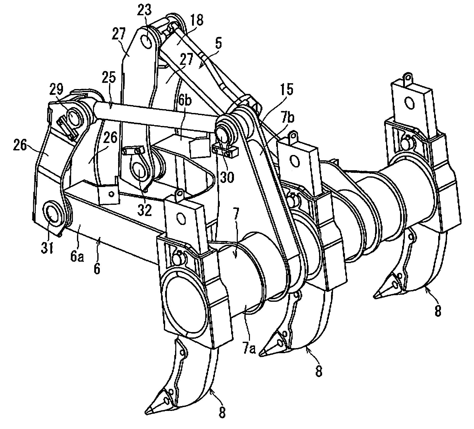
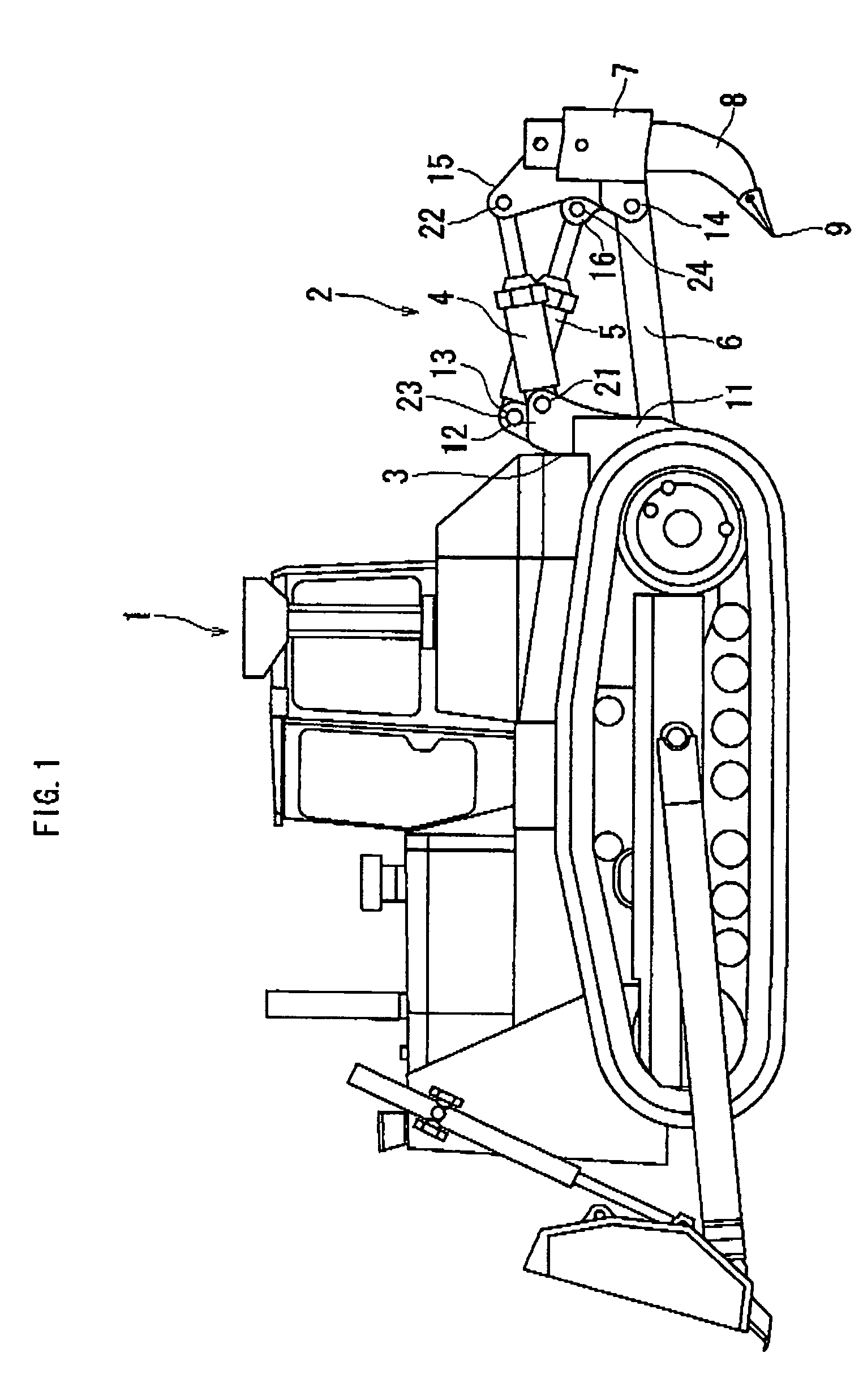
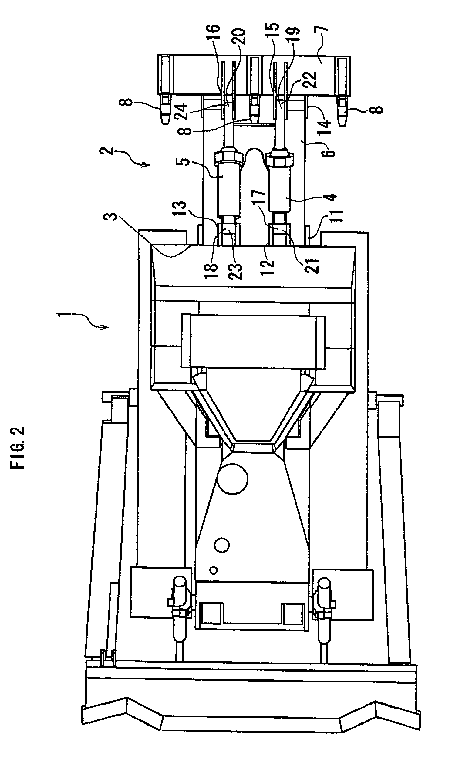
[0028]A concrete embodiment of the ripping device according to the present invention will now be described in details with reference to the drawings. One embodiment of the present invention is illustrated in FIGS. 1 and 2. FIG. 1 is a side view of a bulldozer 1 mounted with a ripping device 2, and FIG. 2 is a plan view of the bulldozer 1. As illustrated in FIGS. 1 and 2, one end of an arm 6 is pivotally attached to a vehicle body rear portion 3 of the bulldozer 1 through a bracket 11, and the other end of the arm 6 is pivotally attached to a lower portion 14 of a beam 7 including three shanks 8. Upward of the arm 6, a hydraulic tilt cylinder 4 and a hydraulic lift cylinder 5 are mounted and connected between the vehicle body rear portion 3 and the beam 7 in a parallel manner in a traveling direction when seen from the top of the vehicle body.

[0029]A bottom-sided base end 17 of the tilt cylinder 4 is pivotally attached to the vehicle body rear portion 3 by means of a bracket 12. A ro...


PUM


Abstract

A ripper assembly is arranged in that one end of an arm is pivotally attached to a vehicle body while a beam comprised with shanks is pivotally attached to the other end of the arm, and in that a tilt cylinder and a lift cylinder are respectively interposed between the vehicle body and the beam at a position upward of the arm. One end side of the lift cylinder is pivotally attached, on a vehicle body side, at a position upward of a vehicle body-sided pivotally supporting portion of the tilt cylinder. The other end side of the lift cylinder is pivotally attached, on a beam side, at a position downward of a beam-sided pivotally supporting portion of the tilt cylinder.

Description

BACKGROUND OF THE INVENTION[0001]1. Field of the Invention[0002]The present invention relates to a ripping device, and particularly to a ripping device that is used for ripping hard soil and soft rocks as a rear implement for use in an earthworking machine.[0003]2. Description of the Prior Art[0004]A prevailing type of a conventional ripping device was a ripper assembly of four-joint link type in which arms are coupled between lower portions of brackets provided at a vehicle body rear portion of a bulldozer and a lower portion of a beam provided with shanks, and in which hydraulic tilt cylinders are mounted between upper portions of the brackets and an upper portion of the beam. In such a ripping device, hydraulic lift cylinders for coupling the brackets and the beam were mounted between the arms and the hydraulic tilt cylinders. The tilt cylinders are mainly used for moving the shanks backward and forward, and the shaft cylinders for moving the shanks up and down. The brackets are ...

Claims


Application Information

Patent Timeline
Patent Type & Authority Patents(United States)
IPC IPC(8): A01B13/08E02F5/32E02F9/28
CPCE02F3/7609E02F5/32
Inventor MATSUMOTO, NORIHISAARAKAWA, KAZUYA
Owner KOMATSU LTD
Why Eureka
Try Eureka