Active camera apparatus and robot apparatus
a camera and robot technology, applied in the field of active camera apparatus and robot apparatus, can solve the problems of large parts of the active camera apparatus including the camera actuator, and the camera actuator is not protected from the external environmen
- Summary
- Abstract
- Description
- Claims
- Application Information
AI Technical Summary
Benefits of technology
Problems solved by technology
Method used
Image
Examples
first embodiment
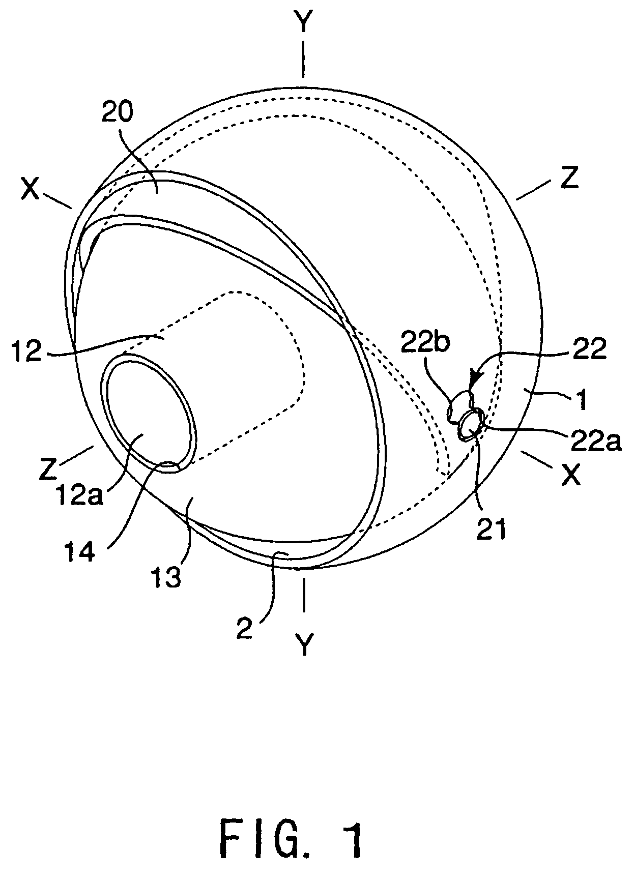
[0048]FIGS. 4A˜4C are schematic diagrams of linking situation between the camera support member 13 and the open-close member 20 according to the FIG. 4A shows a situation before rotating the camera support member 13. FIG. 4B shows a situation of rotation of the camera support member 13. FIG. 4C shows another situation of rotation of the camera support member 13.
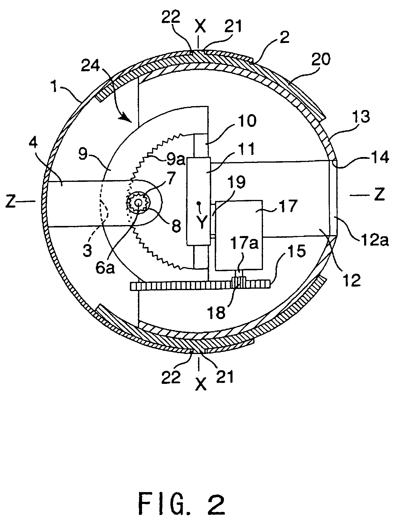
[0049]As shown in FIGS. 4A˜4C, the open-close member 20 and the camera support member 13 are connected by a linking mechanism 23. The linking mechanism 23 is comprised of an engagement pin 23a set on an outer surface of the camera support member 13 and an engagement hole 23b set on the open-close member 20.
[0050]The engagement pin 23a is formed as a round section and located in a space between the camera support member 13 and the outer body 1. On the other hand, the engagement hole 23b is formed as a short length along a rotation direction around the X axis and a long length along a rotation direction around the Y axis (show...
second embodiment
[0061]FIGS. 6A and 6B are schematic diagrams of components of the active camera apparatus according to the present invention. FIG. 6A shows an outward appearance by cutting the active camera apparatus. FIG. 6B shows a section of the active camera apparatus.
[0062]FIGS. 7A˜7C are schematic diagrams of closing situation of the opening 2 of the outer body 1 by the open-close member 20 according to the second embodiment. FIG. 7A shows a situation that the opening 2 of the outer body 1 is fully opened. FIG. 7B shows a situation that the opening 2 of the outer body 1 is slightly covered by the open-close member 20. FIG. 7C shows a situation that the opening 2 of the outer body 1 is fully closed by the open-close member 20.
[0063]In the second embodiment, as shown in FIGS. 6A and 6B, a torsion spring 31 is inter-carried between the support pin 21 and the support hole 22. The torsion spring 31 energizes the open-close member 20 along a closing direction of the opening 2 of the outer body 1, i...
third embodiment
[0073]In the third embodiment, as shown in FIG. 9, the camera 12 includes an imaging device 40, a first lens 42 and a second lens 43 each forming an image of the outside of the outer body 1 onto the imaging device 40, and a lens actuator 44. The first lens 42 and the second lens 43 are moved along an optical direction (front and rear direction) of the camera 12 by the lens actuator 44. Briefly, focus and optical zoom can be automatically executed.
[0074]As shown in FIG. 10, the lens actuator 44 includes an actuator 45 such as an electrostatic actuator, an image processing unit 46 to generate a target value of lens position by processing image information output from the imaging device 40, an orbit generation unit 49 to generate an orbit value of lens based on the target value output from the image processing unit 46, a control operation unit 50 to generate a command value to an actuator driver 47 based on output from the orbit generation unit 49, and an actuator driver 47 to actuate ...
PUM
 Abstract
Description
Claims
Application Information
 - R&D
- Intellectual Property
- Life Sciences
- Materials
- Tech Scout
- Unparalleled Data Quality
- Higher Quality Content
- 60% Fewer Hallucinations
Browse by: Latest US Patents, China's latest patents, Technical Efficacy Thesaurus, Application Domain, Technology Topic, Popular Technical Reports.
© 2025 PatSnap. All rights reserved.Legal|Privacy policy|Modern Slavery Act Transparency Statement|Sitemap|About US| Contact US: help@patsnap.com


