Terminal block for connecting electrical conductors

Active Publication Date: 2008-12-09
MC TECH GMBH (DE)
View PDF15 Cites 101 Cited by
  • Summary
  • Abstract
  • Description
  • Claims
  • Application Information

AI Technical Summary

Benefits of technology

[0006]It is the object of this invention to provide a terminal block with at least two clamping spring elements i

Problems solved by technology

The disadvantage of this terminal block is that the spring forces are transmitted across the plastic of the insulating housing and, since the plastic deforms under large loads, reliable clamping is not ensured a

Method used


Image

  • Terminal block for connecting electrical conductors
  • Terminal block for connecting electrical conductors
  • Terminal block for connecting electrical conductors

Examples


Embodiment Construction

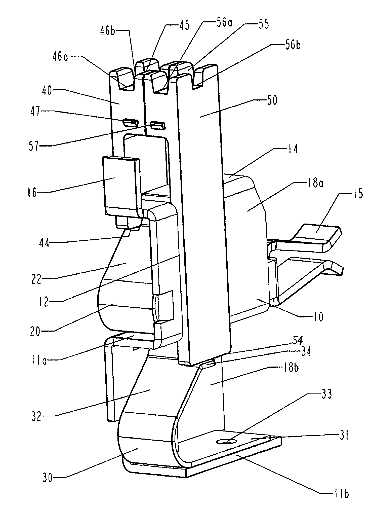
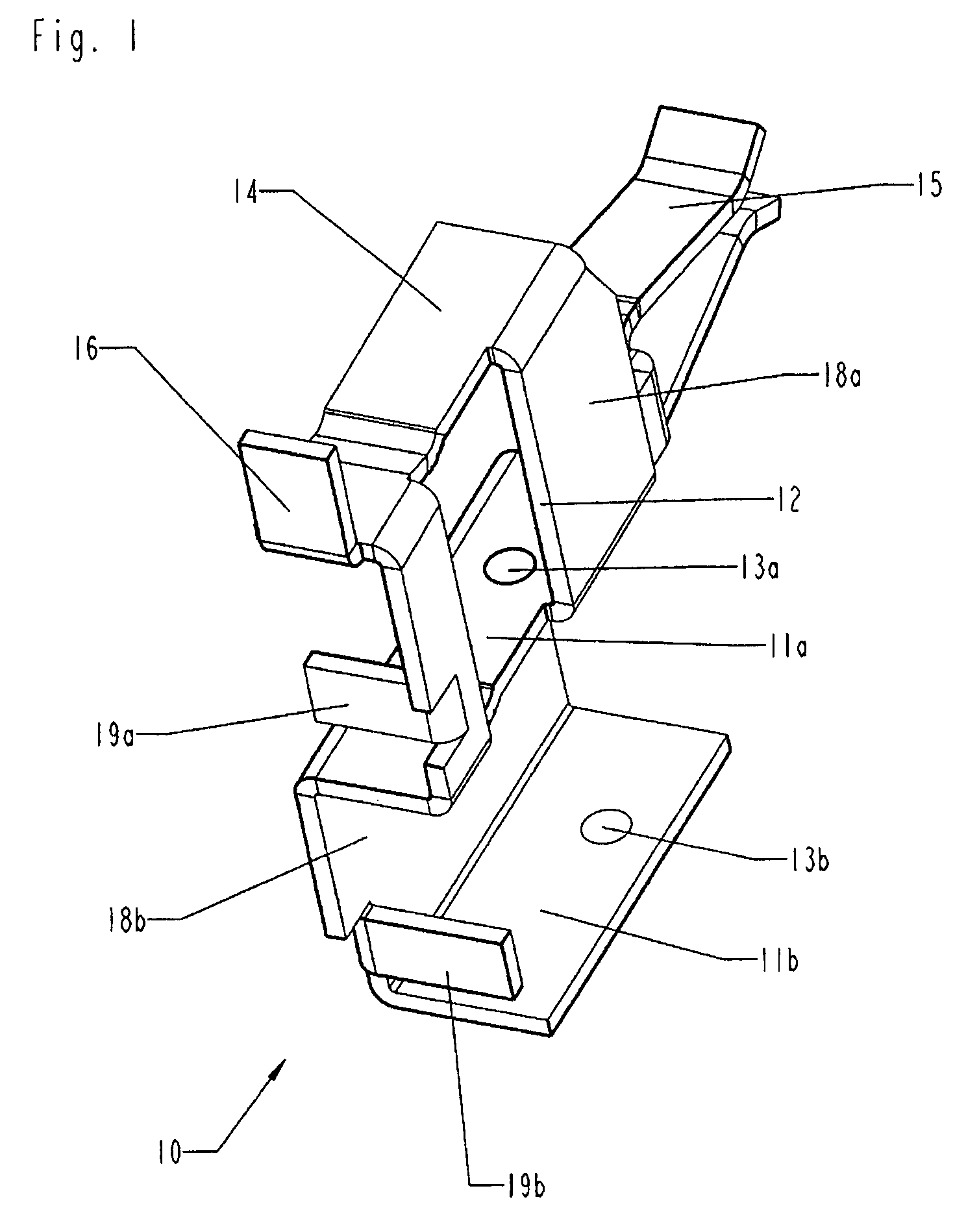
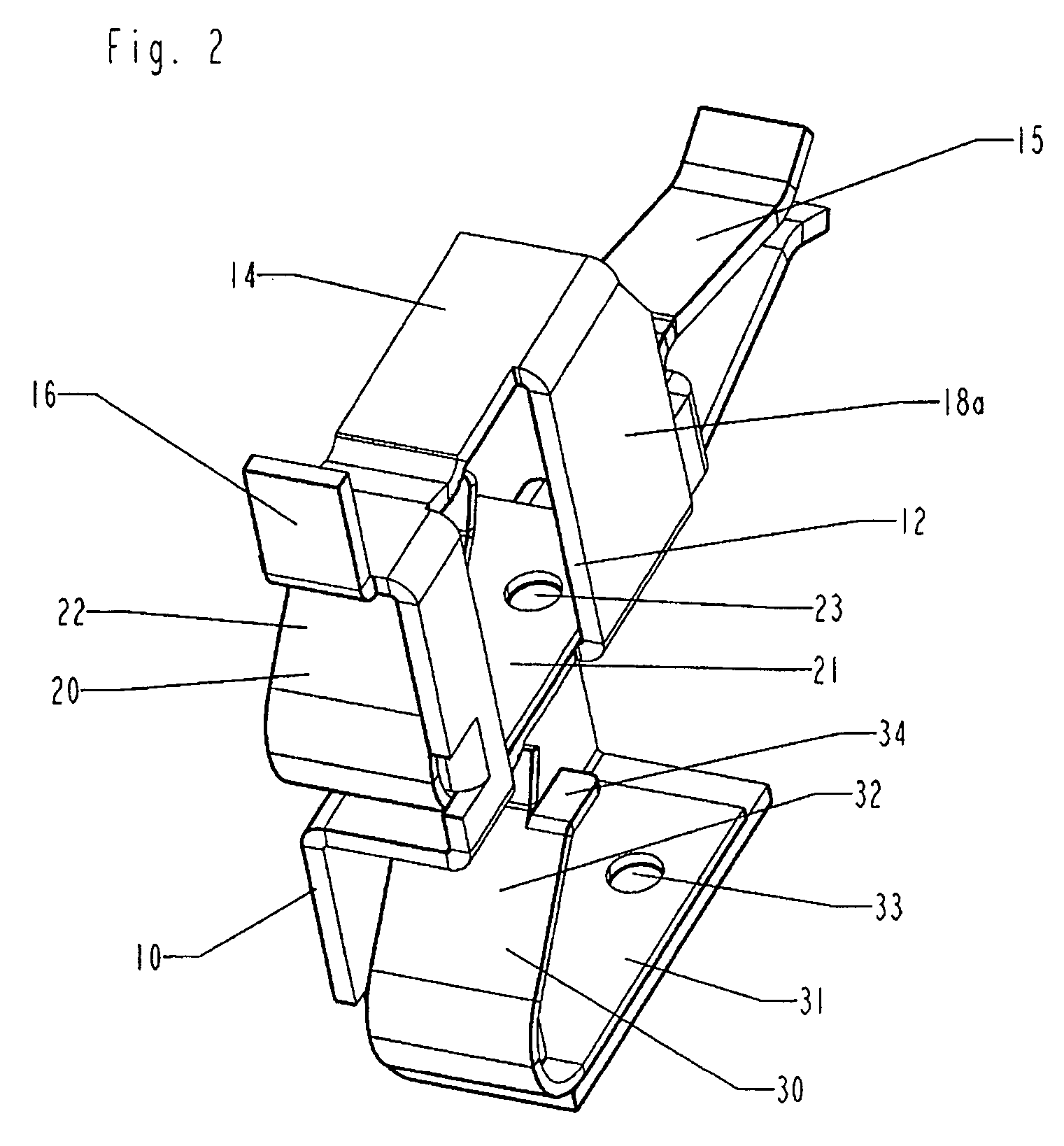
[0039]FIG. 1 shows a perspective view of an S-shaped contact element 10, in which an upper surface 14, a first contact surface 11a and a second contact surface 11b, which are each essentially rectangular, are positioned parallel to each other and are respectively connected to each other via an upper side surface 18a and a lower side surface 18b. The upper side surface 18a connects the upper surface 14 and the first contact surface 11a along one of its longitudinal edges, while the lower side surface 18b connects the first contact surface 11a and the second contact surface 11b along one of its longitudinal edges, wherein, starting at the first contact surface 11a, the side surfaces 18a, 18b are located at the two opposite longitudinal edges of the first contact surface 11a. This results in the essentially S-shaped configuration of the S-shaped contact element 10. The S-shaped contact element 10 can be produced particularly economically as a single piece punched flexural component. Th...


PUM


Abstract

This invention concerns a terminal block for connecting electrical conductors with a first clamping spring element (20) and a second clamping spring element (30) for clamping the electrical conductors, with the first and the second clamping spring elements (20, 30) being displaced vertically with respect to each other and with the two clamping spring elements (20, 30) being electrically connected to each other whereby the two clamping spring elements (20, 30) are electrically connected via an essentially S-shaped contact element (10) into which the two clamping spring elements (20, 30) can be inserted from one side.

Description

CROSS-REFERENCE TO RELATED APPLICATION[0001]Reference is made to co-pending patent application Ser. No. 11 / 730,739, which were commonly owned or subject to an obligation of assignment to the same person at the time the present invention was made.BACKGROUND OF THE INVENTION[0002]1 Field of the Invention[0003]This invention concerns a terminal block for connecting electrical conductors in accordance with the preamble of claim 1.[0004]2 Description of Related Art[0005]DE 197 10 306 A1 discloses a terminal block with two associated clamping points located on top of each other, which are formed by two clamping spring elements formed onto an U-shaped base plate and which are electrically connected to each other. The clamping spring elements are formed by two leaf springs located on the U-shaped base plate, said springs striking the insulating housing of the terminal block. The disadvantage of this terminal block is that the spring forces are transmitted across the plastic of the insulatin...

Claims


Application Information

Patent Timeline
IPC IPC(8): H01R9/22
CPCH01R4/4836H01R11/05H01R9/24H01R13/112H01R4/48365
Inventor WALTER, FRANKSTADLER, HERMANN
Owner MC TECH GMBH (DE)
Why Eureka
Try Eureka