Aircraft engine nacelle inlet having access opening for electrical ice protection system

a technology of electrical ice protection system and aircraft engine, which is applied in the direction of machines/engines, efficient propulsion technologies, power plant inspection panels, etc., can solve the problems of affecting the flight safety of aircraft, affecting the safety of aircraft, so as to promote laminar airflow and promote laminar airflow

Active Publication Date: 2008-12-30
ROHR INC
View PDF24 Cites 27 Cited by
  • Summary
  • Abstract
  • Description
  • Claims
  • Application Information

AI Technical Summary

Benefits of technology

[0011]In yet another aspect, the present invention is directed to a nacelle inlet for an aircraft engine nacelle having an outer barrel, the nacelle inlet comprising electrical heating means for selectively heating at least a portion of a nacelle inlet surface, and access means for selectively accessing the electrical heating means, the access means being configured to promote laminar airflow over the nacelle inlet surface. The access means may comprise at least one service access opening in the outer barrel, and a removable cowling covering the service access opening to thereby promote laminar airflow over the nacelle inlet surface.

Problems solved by technology

The accumulation of ice on aircraft wings and other structural members in flight is a danger that is well known.
Ice accumulation on aircraft engine nacelle inlets also can be problematic.
While a variety of techniques have been proposed for removing ice from aircraft during flight, these techniques have had various drawbacks that have stimulated continued research activities.
One problem associated with providing such electrothermal ice protection systems on the nacelle inlets of aircraft engines involves providing sufficient numbers of access openings in the inner or outer barrels of the engine inlet for accessing and servicing the heating equipment such as heater elements and associated components.
These interruptions or protuberances can interfere with the desired natural laminar airflow into and around the engine inlets, and may contribute to the creation of unwanted noise and drag.

Method used


Image

  • Aircraft engine nacelle inlet having access opening for electrical ice protection system
  • Aircraft engine nacelle inlet having access opening for electrical ice protection system
  • Aircraft engine nacelle inlet having access opening for electrical ice protection system

Examples


Embodiment Construction

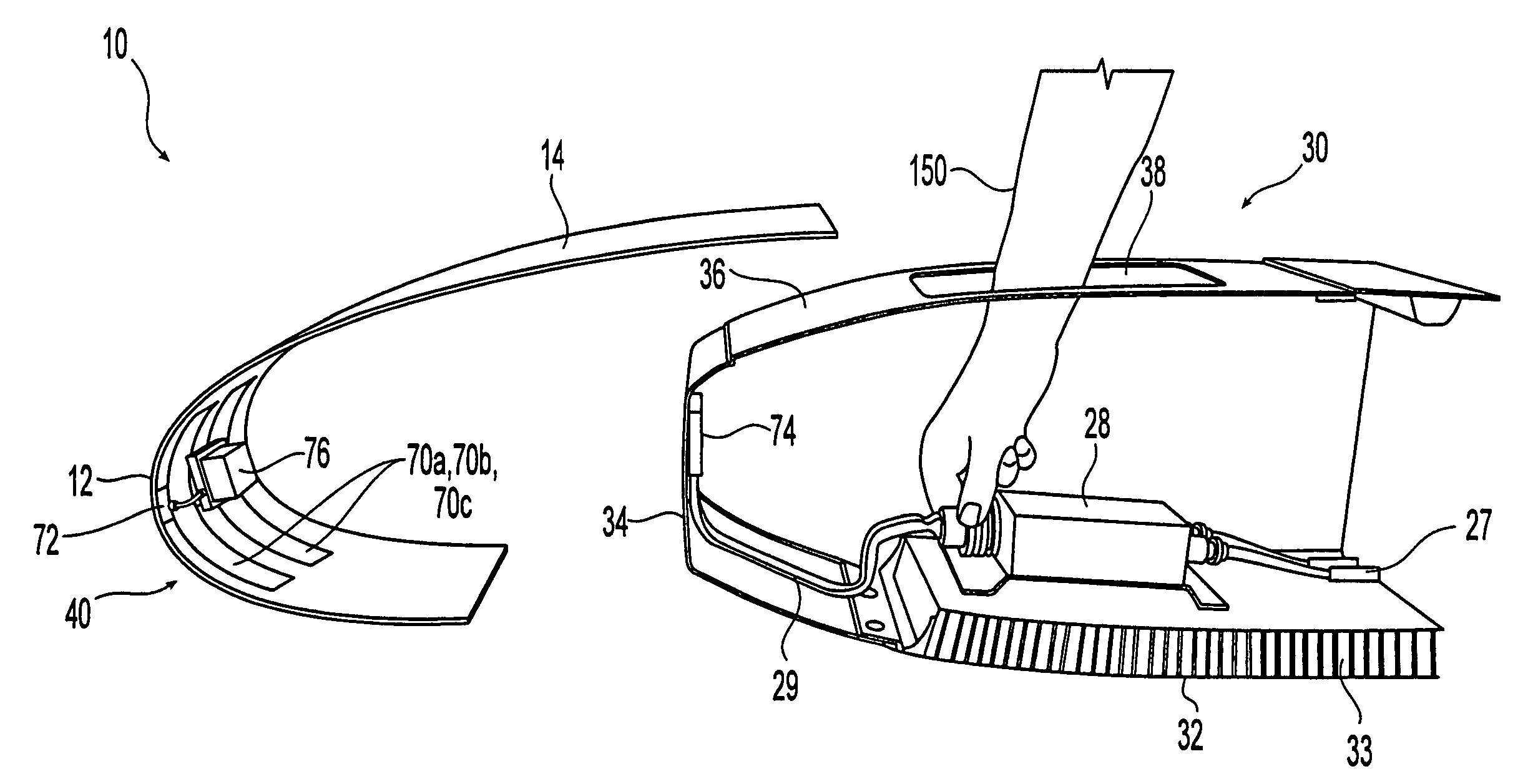
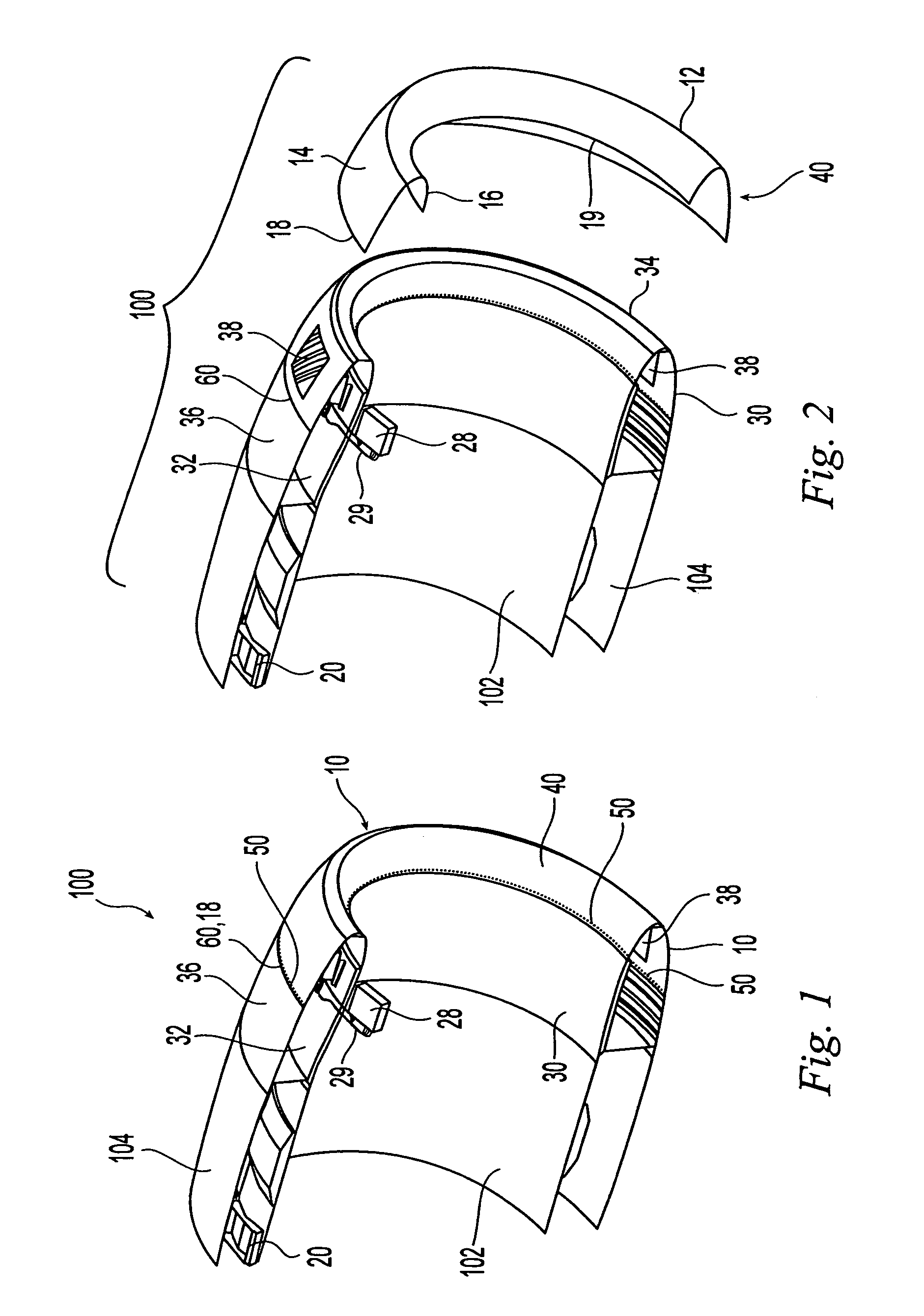
[0023]FIG. 1 shows a portion of an aircraft engine nacelle 100 equipped with one embodiment of a nacelle inlet thermal ice protection assembly 10 according to the invention. The engine nacelle 100 includes a substantially cylindrical inner barrel 102 and a concentric outer barrel 104. The nacelle inlet assembly 10 is disposed on the forward edges of the engine's nacelle inner and outer barrels 102, 104. The nacelle inlet assembly 10 has a smooth aerodynamic shape that substantially promotes natural laminar airflow along the forwardmost surfaces of the engine nacelle 100.

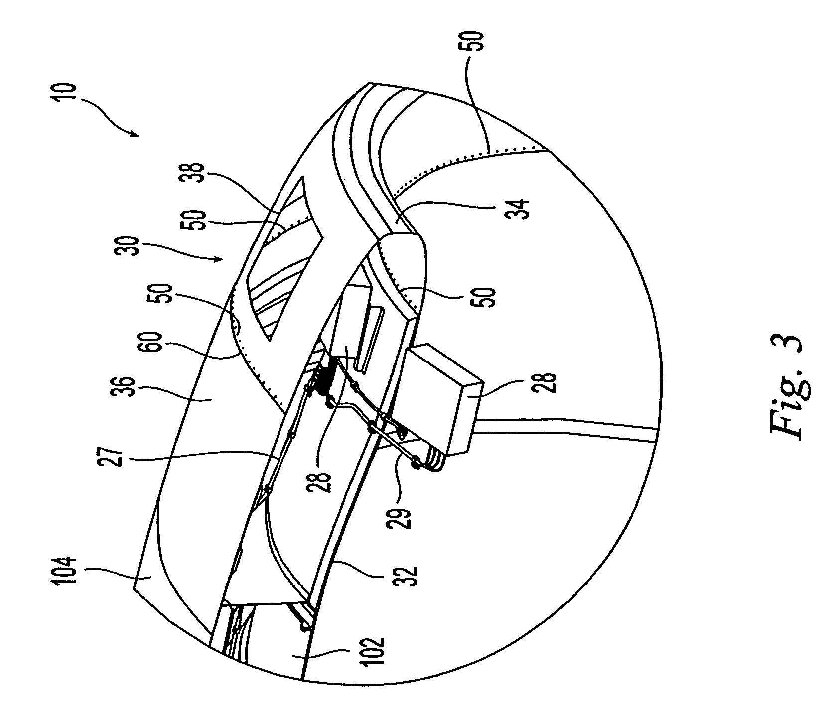
[0024]As shown in FIG. 2, the nacelle inlet assembly 10 includes a removable inlet cowling 40. The inlet cowling 40 includes an inner lip 16, an outer lip 14, and a leading edge portion 12 connecting the two. The aft edge 18 of the outer lip 14 mates with the nacelle inlet assembly 10 along a split line 60. The aft edge 18 and split line 60 are positioned a substantial distance downstream of the leading edge portion ...


PUM


Abstract

An aircraft engine nacelle inlet is provided with an inlet cowling. The inlet cowling includes an inner lip, an outer lip, and a leading edge portion connecting the inner and outer lips. Heating elements are provided proximate the leading edge, either on an inside surface of the cowling or on an outside surface. An inner barrel portion and an outer barrel portion of the nacelle inlet define a space therebetween. Ice protection-related equipment such as controllers, cables, switches, connectors, and the like, may reside in this space. One or more access openings are formed in the outer barrel to enable an operator to gain access to this equipment. The inlet cowling attaches to the inner and outer barrels with its outer lip extending sufficiently far in the aft direction to cover the access opening. When the cowling is removed, the access opening is uncovered, thereby permitting access to the equipment.

Description

RELATED APPLICATIONS[0001]This application is related to U.S. patent application Ser. No. 11 / 111,835, “Aircraft Engine Nacelle Inlet Having Electrical Ice Protection System”, filed even date herewith by the same inventors as the present application, and having substantially the same specification.BACKGROUND[0002]The invention relates to ice protection systems for aircraft, and more specifically relates to an aircraft equipped with a low power high efficiency electrical ice protection system.[0003]The accumulation of ice on aircraft wings and other structural members in flight is a danger that is well known. Such “structural members” include any aircraft surface susceptible to icing during flight, including wings, stabilizers, rotors, and so forth. Ice accumulation on aircraft engine nacelle inlets also can be problematic. Attempts have been made since the earliest days of flight to overcome the problem of ice accumulation. While a variety of techniques have been proposed for removin...

Claims


Application Information

Patent Timeline
Patent Type & Authority Patents(United States)
IPC IPC(8): B64D15/12
CPCB64D15/12B64D29/08F02C7/047B64D2033/0233B64D2033/0273B64D2241/00Y02T50/672Y02T50/60
Inventor LAYLAND, MICHAEL JOHNBROWN, KEITH TOWERS
Owner ROHR INC
Why Eureka
Try Eureka