Check patentability & draft patents in minutes with Patsnap Eureka AI!

Elevating device

a technology of inclination device and inclination plate, which is applied in the direction of instruments, machine supports, other domestic objects, etc., can solve the problem of unsatisfactory inclination adjustment of the devi

Inactive Publication Date: 2009-01-13
CORETRONIC
View PDF5 Cites 8 Cited by
  • Summary
  • Abstract
  • Description
  • Claims
  • Application Information

AI Technical Summary

Benefits of technology

This solution allows for precise adjustment of the projector's inclination angle while maintaining a compact size, as the rack members can be extended in a transverse direction without increasing the projector's thickness, enhancing usability without compromising its compact design.

Problems solved by technology

The aforesaid rack member 26 though can adjust the inclination angle of the outer casing 2 with respect to the support surface, the inclination adjustment thereof is not ideal due to the compact size of the outer casing 2.

Method used


Image

  • Elevating device
  • Elevating device
  • Elevating device

Examples


Embodiment Construction

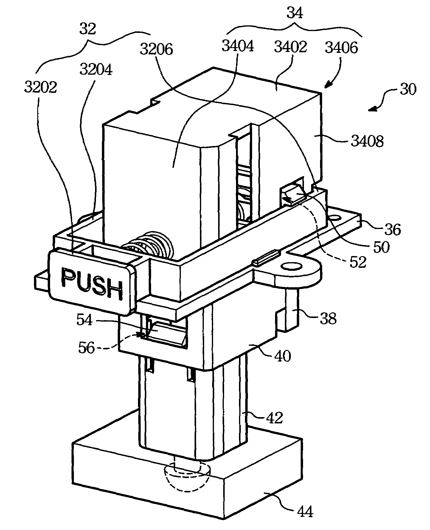
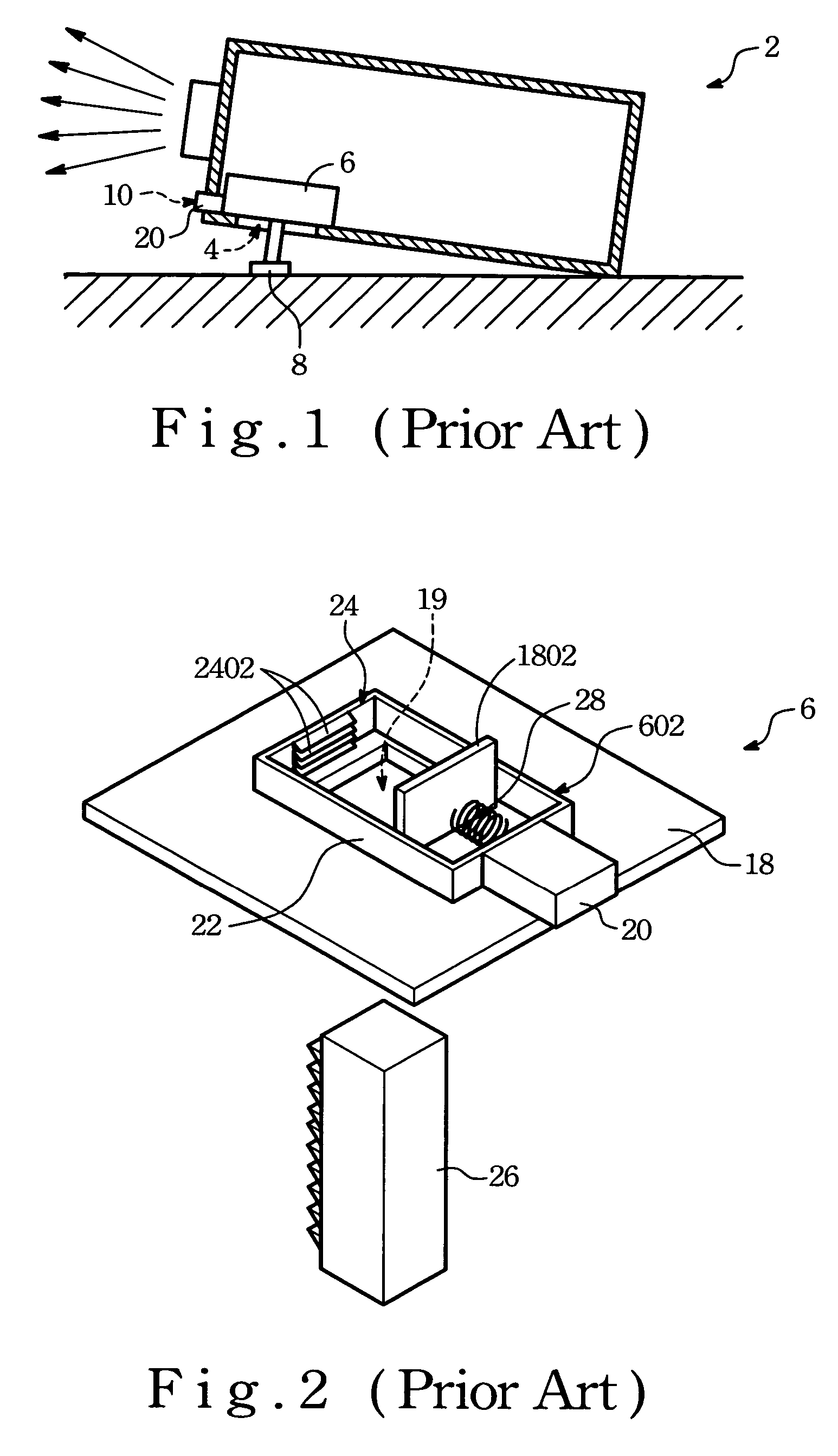
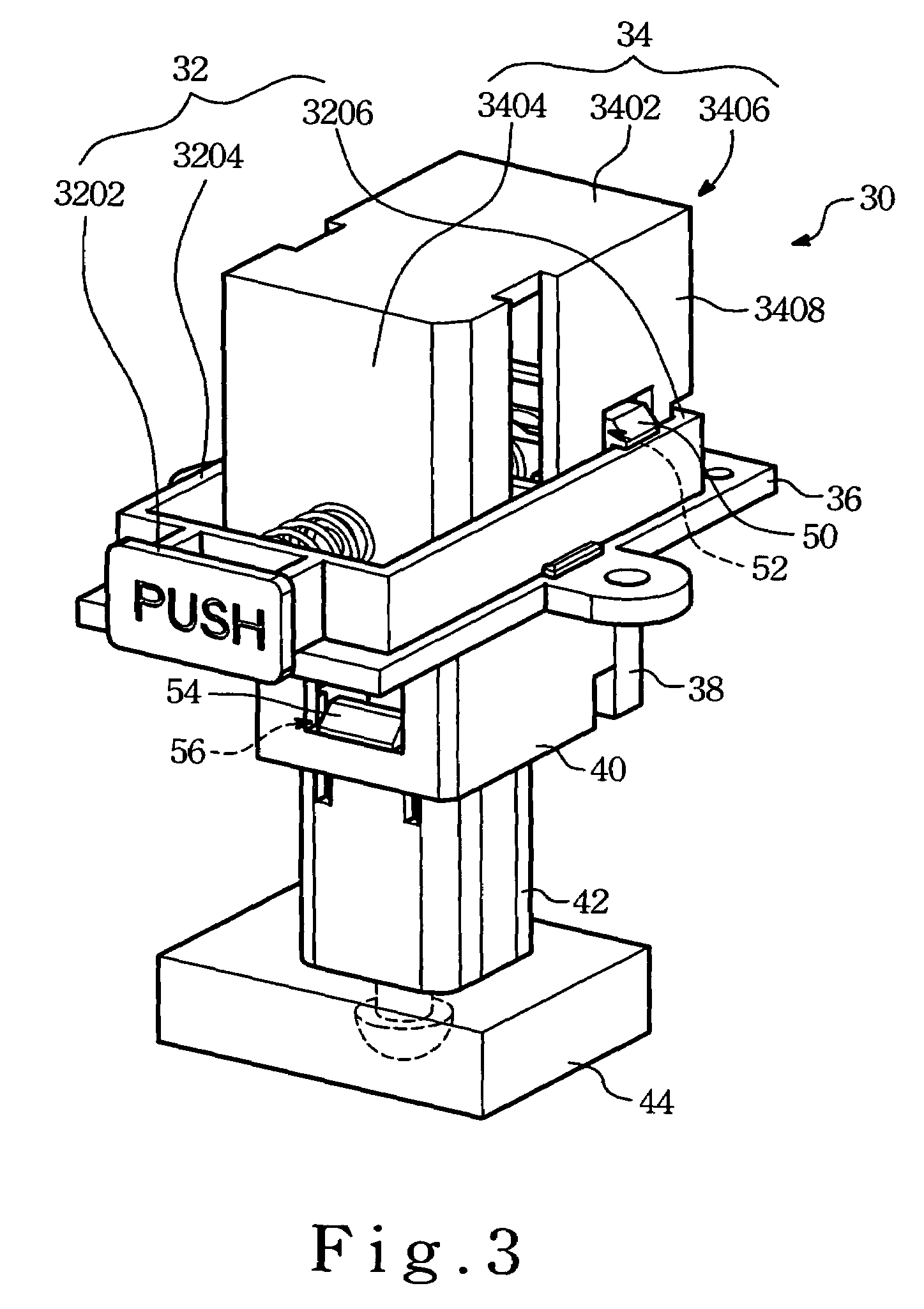
[0015]Referring to FIGS. 3 and 4, a projector of the present invention includes an outer casing (see FIG. 1) and an elevating device 30 employed in the outer casing in order to adjust an inclination angle of the outer casing with respect to a support surface, as best shown in FIG. 1. The outer casing is provided with a projection lens (not visible) for projecting an image onto a screen away from the outer casing.

[0016]The elevating device 30 includes a base plate 36, a sliding member 32, a first urging member 60, a hollow wall structure 40, a first rack member 38, a second rack member 42, a second urging member 62 and a third urging member 64.

[0017]The base plate 36 is disposed securely on the bottom wall of the outer casing (see FIG. 1), defines a longitudinal direction. The base plate 36 is formed with a through hole 80 that extends in a transverse direction with respect to the longitudinal direction. The base plate 36 has a top cover 34 protruding upwardly therefrom to shield the...


PUM


Abstract

An elevating device includes first and second rack members interconnecting each other in such a manner to protrude downwardly from a lower opening of an outer casing in a double-step manner so as to be supported on a support surface. The elevating device adjusts an inclination angle of the outer casing relative to the support surface.

Description

FIELD OF THE INVENTION[0001]The invention relates to an elevating device, more particularly to a elevating device for use in a projector.BACKGROUND OF THE INVENTION[0002]Referring to FIG. 1, a conventional projector is shown to include an outer casing 2 provided with a projection lens for projecting an image onto a screen. The outer casing 2 is further provided with an elevating device 6 for adjusting an inclination angle of a front end of the outer casing 2 with respect to a support surface. The outer casing 2 has a front wall formed with a front opening 10 and a bottom wall formed with a lower opening 4.[0003]Referring to FIGS. 1 and 2, the elevating device 6 includes a base plate 18, a generally rectangular push member 602, a partition 1802, an urging member 28, a rack member 26. The base plate 18 is disposed securely on the bottom wall of the outer casing 2, and is formed with a rack aperture 19 in aligned with the lowering opening 4. The push member 602 is disposed slidably on ...

Claims


Application Information

Patent Timeline
Patent Type & Authority Patents(United States)
IPC IPC(8): G03B21/14F16M11/04
CPCF16M11/10G03B21/14F16M2200/024G03B21/145
Inventor HSU, WEI-POLIU, CHIA-LUNCHANG, TAI-LI
Owner CORETRONIC
Features
  • R&D
  • Intellectual Property
  • Life Sciences
  • Materials
  • Tech Scout
  • Unparalleled Data Quality
  • Higher Quality Content
  • 60% Fewer Hallucinations
Learn More