Routing clip elements with a living hinge and interlocking closure

a technology of routing clips and hinges, which is applied in the direction of machine supports, coupling device connections, applications, etc., can solve the problems of increasing the price of individual components and the cost of the vehicle manufacturer, and achieve the effect of reducing or eliminating the number of routing clips and brackets

Inactive Publication Date: 2009-03-03
INT TRUCK INTPROP LLC
View PDF9 Cites 9 Cited by
  • Summary
  • Abstract
  • Description
  • Claims
  • Application Information

AI Technical Summary

Benefits of technology

[0005]It is the object of the present invention to reduce or eliminate the number of routing clips and brackets used by vehicle manufacturers by providing a modular system of clip sub-components that can be assembled as needed in order to meet the majority of such routing and clipping requirements. In order to accomplish this, a series of interlocking molded polymer elements are used. Typically, the polymer selected will be high-impact and ultraviolet decay resistant. The elements may be divided into several types, including mounting elements, straight extension elements, angled elements, and clip elements. They are provided with a common set of interlocking features, such as a barbed protrusion or protrusions that fit into a recess or slot, or posts that fit into corresponding holes, or even a lateral T-section that slides into a corresponding lateral T-slot. In any given embodiment, the interlocking features are designed in such a way that the parts lock together when assembled, preferably with a positive audible or tactile feedback, such that the elements “snap-together”. Further, the interlocking features may be configured so that they are releasable by manual manipulation, or by use of a tool.
[0006]The mounting element may simply be a body with a hole, which hole is provided in several common sizes, in increments of half a millimeter in the smaller sizes, full millimeters in the larger sizes, or sixteenths of an inch. In this way, a common fastener may be used to attach the mounting element to the vehicle. The mounting element may be provided with an overmolded metal insert for strength in compression, so that the common fastener may be tightened securely. The hole, whether in the parent molded material of the mounting element, or whether in the overmolded metal insert, may be threaded with or without a locking feature, so that only a male common threaded fastener need be used to attach the mounting element to the vehicle. The threads provided may be in metric or SAE standard. Alternately, the mounting element may be provided with a mounting stud, whether formed out of the parent molded material, or as an overmolded or otherwise attached metal insert. The stud may be provided in several sizes and lengths, with metric or SAE standard thread. Further embodiments of mounting elements include elements provided with a fir-tree or rosebud press-in type feature insertable into a hole provided in the vehicle structure, and elements provided with a high-bonding adhesive backing.

Problems solved by technology

This is inefficient from a manufacturing standpoint, and results in greater costs to the vehicle manufacturer, both in the price of the individual components, as well as in overhead costs associated with inventory and distribution of service parts.

Method used


Image

  • Routing clip elements with a living hinge and interlocking closure
  • Routing clip elements with a living hinge and interlocking closure
  • Routing clip elements with a living hinge and interlocking closure

Examples


Embodiment Construction

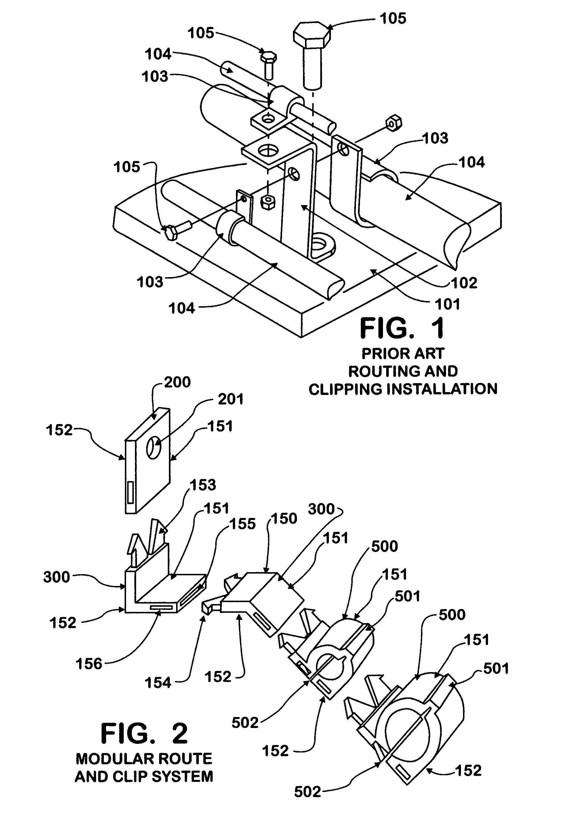
[0033]FIG. 1 shows a typical prior art routing and clipping installation. A standoff bracket 102 of complex shape is attached to a vehicle mounting surface 101. Routing clips 103 of various sizes are attached to the standoff bracket 102, using common fasteners 105, also of various sizes. Lines to be routed 104 are securely held in place by the clips 103.

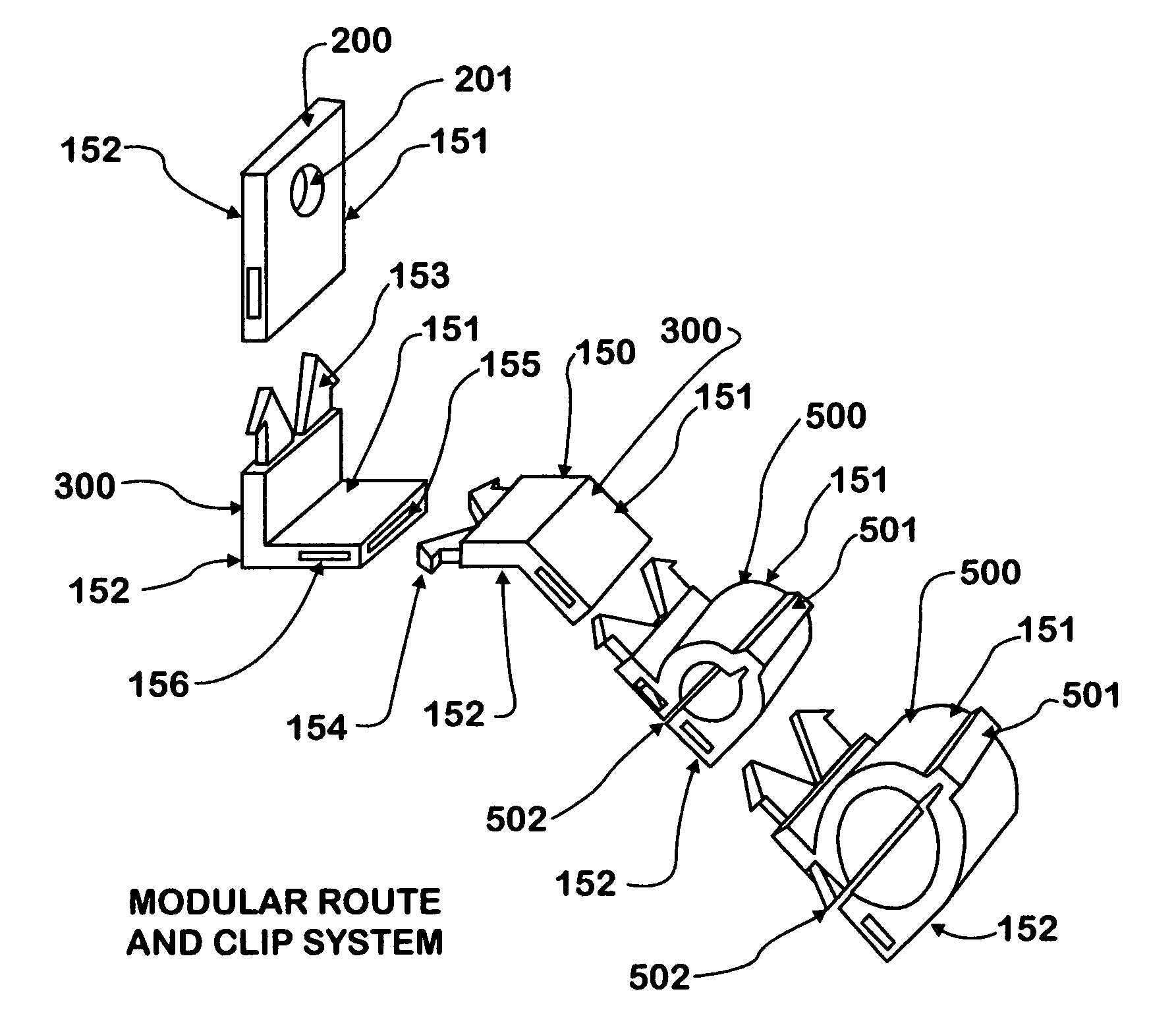
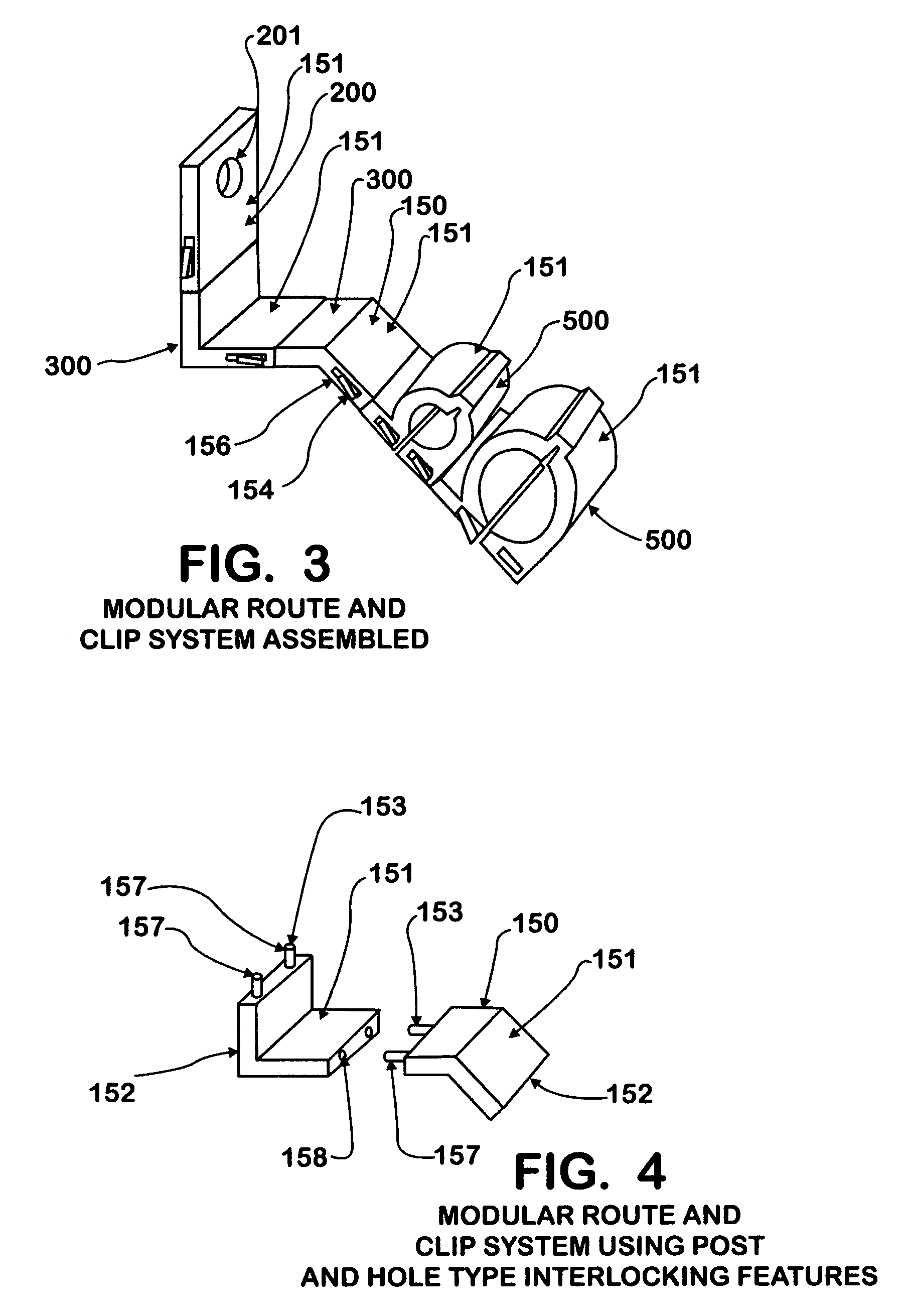
[0034]FIG. 2 shows an embodiment of the present invention, a modular route and clip system 150 comprised of modular route and clip system elements 151. Each modular route and clip system element 151 is provided with an element body 152 and interlocking features 153, by means of which the modular route and clip system elements 151 may be connected one to the next. The modular route and clip system elements 151 shown in FIG. 2 are shown projected from their assembled positions, so that the nature of their interlocking relationship may be more readily shown. The interlocking features 153 of the embodiment shown in FIG. 2 are made up of ...


PUM


Abstract

A modular system of routing clip subcomponents having compatible interlocking features allows for as-needed assembly of multiple clips and extensions, thereby eliminating the need for specialized standoff brackets and clipping devices when routing vehicle wires, hoses, tubes, cables, harnesses, and the like. Generally molded from high-impact and decay resistant polymers, the elements of the modular system are inexpensive to manufacture and simple to assemble by hand.

Description

BACKGROUND OF THE INVENTION[0001]1. Field of the Invention[0002]This invention relates to vehicle hose, tube, and wiring clips or retainers, and more particularly, to a modular system of individual clip or retainer sub-components which can be assembled in multiple configurations in order to meet varying installation requirements. The sub-components are molded from plastic or similar material, and are formed in such a way that they snap easily and securely together, interchangeably. In this way, the need for vehicle manufacturers to manufacture and stock a large number of specialized clips, standoffs, and extensions is eliminated.[0003]2. Description of the Related Art[0004]Ground traveling vehicles possess a large number of wires, hoses, tubes, cables, electrical harnesses, lines, and the like, which must be carefully clipped and routed to avoid chafing, interference with vehicle componentry, or exposure to adverse environmental factors, such as high temperatures. In order to accomp...

Claims


Application Information

Patent Timeline
Patent Type & Authority Patents(United States)
IPC IPC(8): H01R4/50
CPCF16L3/1033B60R16/0215F16L3/222H02G3/32H02G3/305
Inventor NIX, GERALD J.TORRES, LUIS A.
Owner INT TRUCK INTPROP LLC
Why Eureka
Try Eureka