Fuel injection apparatus having fuel supplier for displacement amplifying chamber

a technology of displacement amplifying chamber and fuel injection apparatus, which is applied in the direction of fuel injecting pump, liquid fuel feeder, machine/engine, etc., can solve the problems of low-pressure fuel in the low-pressure passage, mechanism cannot inject high-pressure fuel, and the amplifying chamber cannot function normally, so as to minimize the manufacturing cost of the fuel injection apparatus

Inactive Publication Date: 2009-04-21
DENSO CORP
View PDF12 Cites 4 Cited by
  • Summary
  • Abstract
  • Description
  • Claims
  • Application Information

AI Technical Summary

Benefits of technology

[0017]It is, therefore, a primary object of the present invention to provide a fuel injection apparatus for an internal combustion engine, which can promptly fill up a displacement amplifying chamber formed therein with low-pressure fuel after start of the engine, thereby initiating fuel injection in a timely manner.
[0020]Having the fuel supplier, it is possible for the fuel injection apparatus to minimize the time required to fill up the displacement amplifying chamber with the low-pressure fuel after start of the engine, thereby initiating the fuel injection in a timely manner.
[0022]With the above configuration, it is possible to regulate both the fuel pressures in the high-pressure and low-pressure passages and to reliably fill up the displacement amplifying chamber with the low-pressure fuel under the second predetermined pressure.
[0024]With the above configuration, it is possible to utilize the pressure reducing valve that has already existed in the common rail fuel injection system, thereby minimizing the manufacturing cost of the fuel injection apparatus.

Problems solved by technology

However, when there is left only an extremely small amount of the fuel in the fuel tank, the feed pump will suck in air along with the fuel from the fuel tank.
However, when the fuel injection system is stopped along with the engine, the low-pressure fuel in the low-pressure passage comes to leak out via a check valve that is hydraulically connected to the low-pressure passage to regulate the fuel pressure therein to the predetermined pressure.
Consequently, during the certain time period, the large air bubbles are compressed within the displacement amplifying chamber, so that the displacement amplifying chamber cannot function normally, and thus the fuel injection mechanism cannot inject the high-pressure fuel into the cylinder of the engine in a timely manner.
Consequently, with the limited amount of the fuel, it is difficult to promptly fill up the hydraulic coupler 29 after start of the engine.

Method used


Image

  • Fuel injection apparatus having fuel supplier for displacement amplifying chamber
  • Fuel injection apparatus having fuel supplier for displacement amplifying chamber
  • Fuel injection apparatus having fuel supplier for displacement amplifying chamber

Examples


Embodiment Construction

[0034]The preferred embodiment of the present invention will be described hereinafter with reference to FIGS. 1-4.

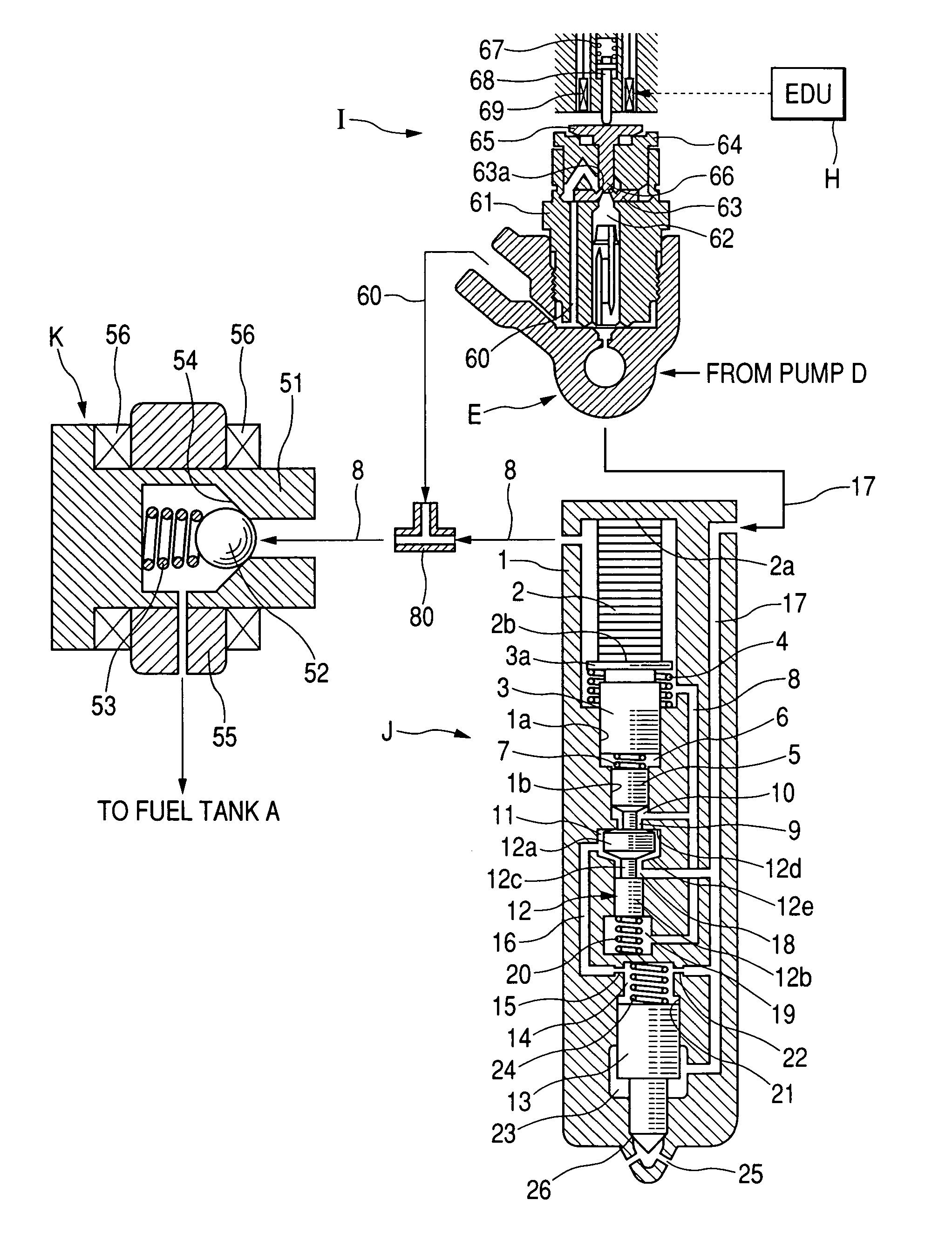
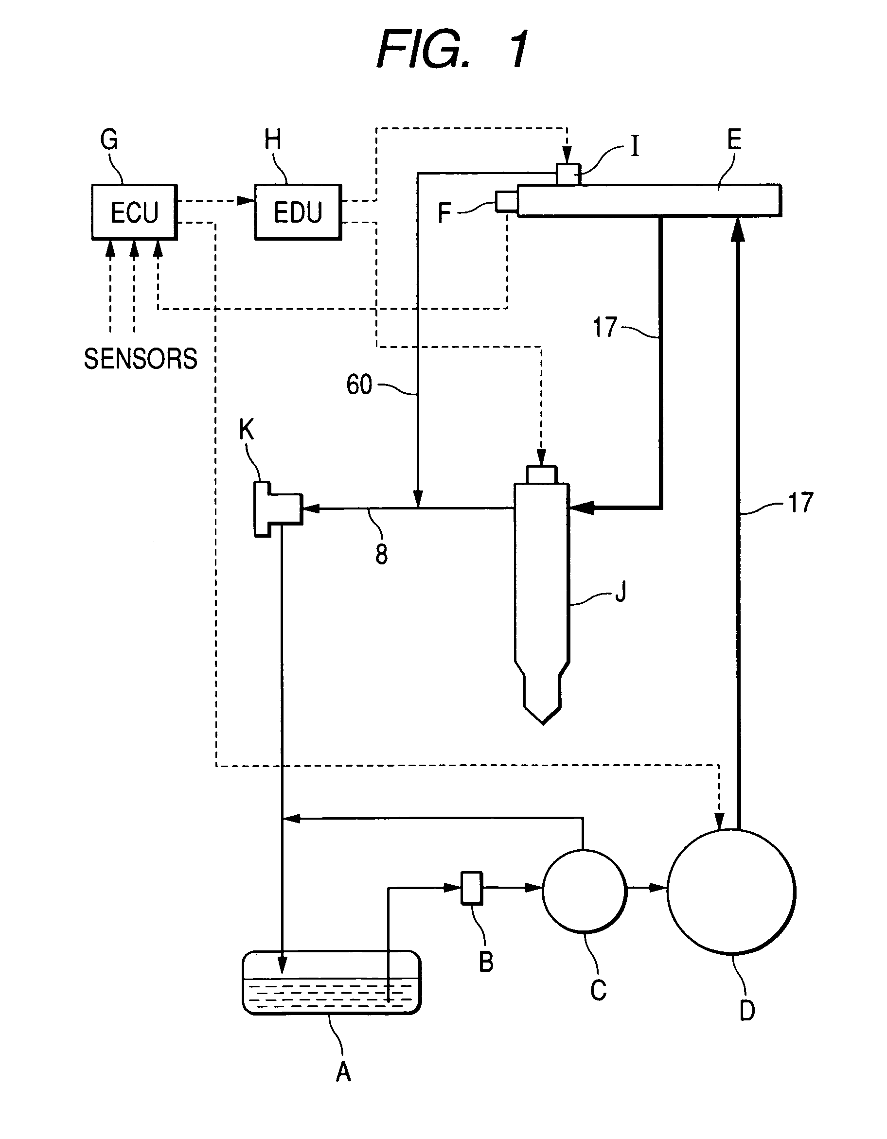
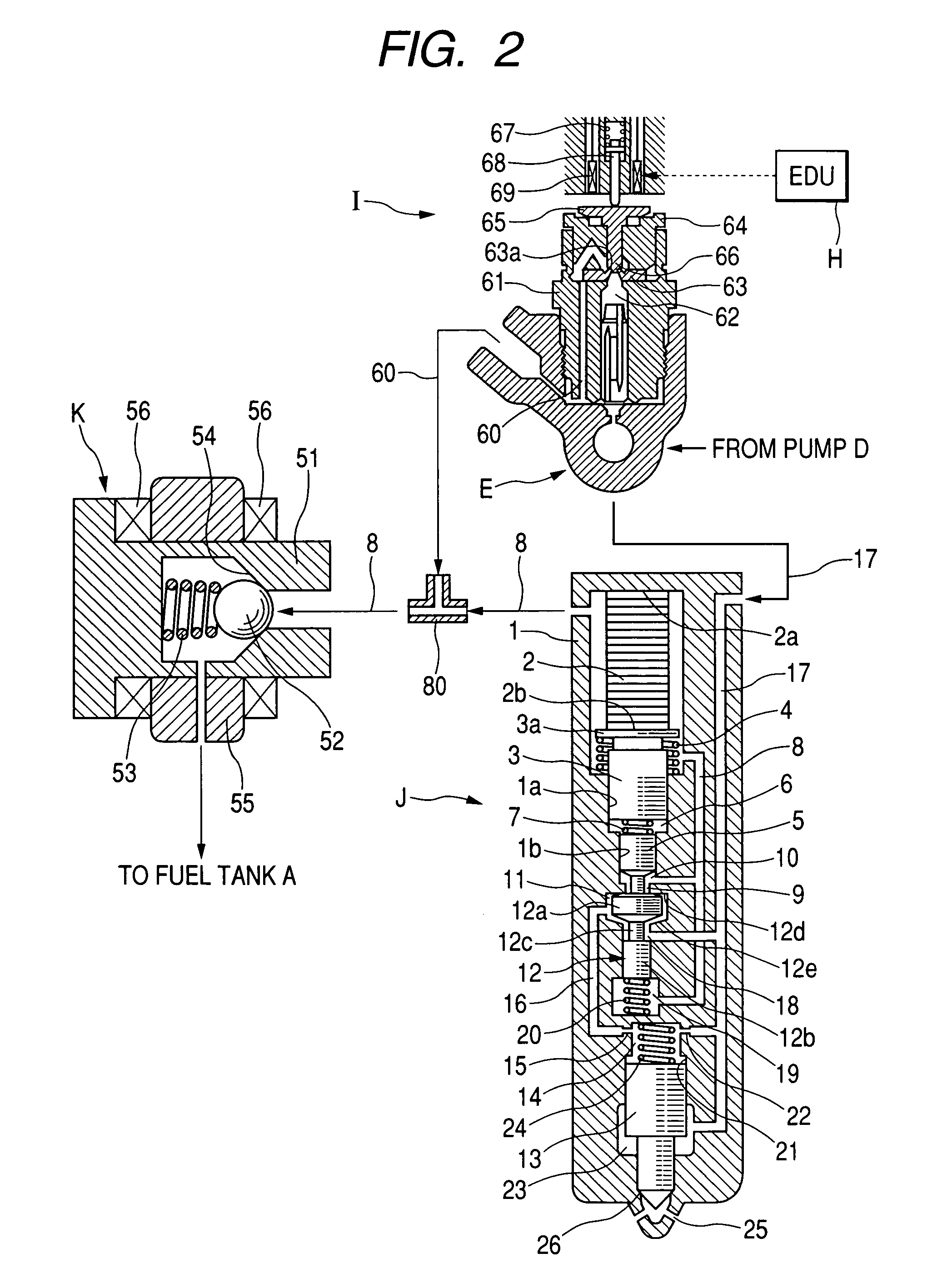
[0035]FIG. 1 shows the overall configuration of a common rail fuel injection system for a diesel engine of a motor vehicle, which incorporates therein a fuel injection apparatus according an embodiment of the present invention.

[0036]As shown in FIG. 1, fuel contained in a fuel tank A is drawn by a feed pump C through a filter B and fed to a high-pressure pump D.

[0037]The high-pressure pump D pressurizes the fuel to a high pressure and supplies the resultant high-pressure fuel to a common rail E. The high-pressure pump D is driven by the engine (not shown) and has a sufficiently large discharge rate, so that it can quickly fill up the common rail E with the high-pressure fuel after start of the engine.

[0038]A pressure sensor F is installed to the common rail E to sense the fuel pressure in the common rail E. The pressure sensor F provides a pressure signal indicative of t...


PUM


Abstract

According to the present invention, a fuel injection apparatus includes a high-pressure passage, a low-pressure passage, an actuator, a first and a second piston, a displacement amplifying chamber, a fuel injection mechanism, and a fuel supplier. The high-pressure passage is configured to be filled with high-pressure fuel. The low-pressure passage is configured to be filled with low-pressure fuel. The first piston is configured to be displaced by the actuator. The displacement amplifying chamber communicates with the low-pressure passage and works to amplify and transmit to the second piston a displacement of the first piston by means of the low-pressure fuel therein. The fuel injection mechanism is configured to inject the high-pressure fuel into a cylinder of an internal combustion engine in response to the displacement of the second piston. The fuel supplier works to supply the high-pressure fuel from the high-pressure passage through pressure reduction directly to the low-pressure passage.

Description

CROSS-REFERENCE TO RELATED APPLICATION[0001]This application is based on and claims priority from Japanese Patent Application No. 2005-297412, filed on Oct. 12, 2005, the content of which is hereby incorporated by reference into this application.BACKGROUND OF THE INVENTION[0002]1. Technical Field of the Invention[0003]The present invention relates to fuel injection apparatuses or systems for injecting fuel into cylinders of internal combustion engines. More particularly, the invention relates to a fuel injection apparatus for a diesel engine of a motor vehicle, which has a displacement amplifying chamber formed therein and includes a fuel supplier for promptly filling up the displacement amplifying chamber with low-pressure fuel after start of the engine.[0004]2. Description of the Related Art[0005]An existing fuel injection apparatus, which is incorporated in a common rail fuel injection system for a diesel engine of a motor vehicle, includes a high-pressure passage, a low-pressure...

Claims


Application Information

Patent Timeline
Patent Type & Authority Patents(United States)
IPC IPC(8): F02M63/00F02M69/54
CPCF02M57/025F02M59/105F02M63/0026
Inventor TOYOSHIMA, YOSHIO
Owner DENSO CORP
Why Eureka
Try Eureka