Radio receiving apparatus

a technology for receiving apparatus and radio receivers, applied in the direction of transmission monitoring, instruments, anti-theft devices, etc., can solve the problems of large circuit of radio receiving apparatus, large cost, no literature available, etc., and achieve the effect of small circuit and simple circui

Inactive Publication Date: 2009-04-21
MURATA MFG CO LTD
View PDF36 Cites 3 Cited by
  • Summary
  • Abstract
  • Description
  • Claims
  • Application Information

AI Technical Summary

Benefits of technology

[0011]In order to overcome the problems described above, preferred embodiments of the present invention provide an inexpensive radio receiving apparatus which has a simple and small circuit despite the fact that a plurality of receiving antennas are used.
[0018]The radio receiving apparatus described above advantageously has a small circuit despite the fact that a plurality of receiving antennas are used, and exhibits a greatly increased likelihood of a signal being successfully received. Furthermore, the surface acoustic wave device functioning as band-pass filters for simultaneously input signals contribute to a reduction in the number of components of the radio receiving apparatus.

Problems solved by technology

This diversity switching, however, may require two or more detector circuits and a select switch, leading to a complicated and large circuit of the radio receiving apparatus, which thus becomes expensive.
No literature is available which introduces a radio receiving apparatus that neither uses the CDMA system nor carries out diversity switching.
Furthermore, there is no known literature which discloses an RKE receiver using the diversity system.
For this reason, it is difficult to apply the disclosed systems to radio receiving apparatuses which use FSK modulation and ASK modulation, such as RKE receivers.
Furthermore, diversity switching, which readily causes the receiving apparatus adopting it to become large for the reasons described above, is not suitable for a radio receiving apparatus, such as an RKE receiver, whose function is so simple as to handle only a small amount of communication information and which therefore must be inexpensive.

Method used


Image

  • Radio receiving apparatus
  • Radio receiving apparatus
  • Radio receiving apparatus

Examples


Embodiment Construction

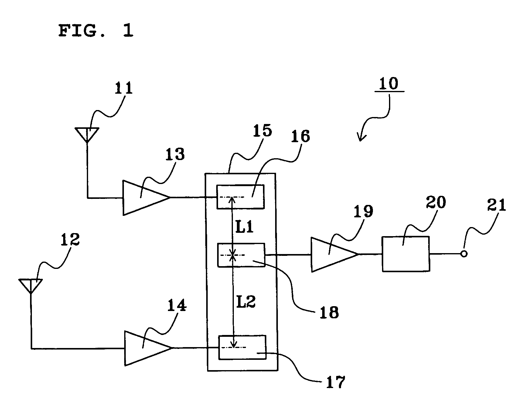
[0026]FIG. 1 is a block diagram of a radio receiving apparatus according to a first preferred embodiment of the present invention. A radio receiving apparatus 10 represents an RKE receiver which preferably includes two antennas 11 and 12, three RF amplifiers 13, 14, and 19, a SAW filter 15 as a surface acoustic wave device, a detector circuit 20, and an output terminal 21. The SAW filter 15 includes three inter-digital transducers (abbreviated to IDTs) 16, 17, and 18 arranged in the propagation direction of a surface acoustic wave. The IDTs 16 and 17 are input IDTs and the IDT 18 is an output IDT. The IDT 18 is disposed between the IDTs 16 and 17. A clearance L1 between the IDT 16 and the IDT 18 and a clearance L2 between the IDT 17 and the IDT 18 differ from each other. This design allows one band-pass filter (may be abbreviated to BPF) to be formed between the IDTs 16 and 18 and another BPF to be formed between the IDTs 17 and 18 such that both the BPFs have substantially identica...


PUM


Abstract

A radio receiving apparatus includes two receiving antennas, two upstream RF amplifiers, a SAW filter having two input IDTs and an output IDT, a downstream RF amplifier, and a detector circuit. The antennas are connected to the respective input IDTs via the respective upstream RF amplifiers. The detector circuit is connected via the downstream RF amplifier to the output IDT, which receives a signal from each of the two input IDTs. The distances from the center of the output IDT to the centers of the input IDTs differ from one another. The SAW filter functions as two band-pass filters, two delay circuits connected to the respective band-pass filters, and a combiner circuit for combining the outputs from the delay circuits.

Description

BACKGROUND OF THE INVENTION[0001]1. Field of the Invention[0002]The present invention relates to a radio receiving apparatus for use in, for example, a remote keyless entry (abbreviated to RKE in some cases) system which is intended to successfully receive, at least once, a single radio signal which is transmitted several times at predetermined intervals.[0003]2. Description of the Related Art[0004]A typical radio receiving apparatus, such as those adopting the diversity system, uses two or more antennas for successful reception of a signal. A radio receiving apparatus which uses two or more antennas carries out diversity switching for selecting a signal received with the best conditions from among those signals received by the respective antennas. This diversity switching, however, may require two or more detector circuits and a select switch, leading to a complicated and large circuit of the radio receiving apparatus, which thus becomes expensive. To address this problem, Japanese...

Claims


Application Information

Patent Timeline
Patent Type & Authority Patents(United States)
IPC IPC(8): H04B1/04G07C9/00H04B7/08
CPCB60R25/24G07C9/00182H04B7/084G07C2009/00793G07C2209/61
Inventor KATO, AKIRAKAWABATA, TAKASHI
Owner MURATA MFG CO LTD
Why Eureka
Try Eureka