AC coupling bandwidth switch

a bandwidth switch and receiver circuit technology, applied in the direction of pulse technique, amplitude demodulation, dc level restoring means or bias distort correction, etc., can solve the problem of long settling time for the transient, the property of the signal is problematic, and the switched circuit suffers from a similar problem, so as to reduce the maximum magnitude of the switching transient

Inactive Publication Date: 2010-01-05
INTEL CORP
View PDF18 Cites 3 Cited by
  • Summary
  • Abstract
  • Description
  • Claims
  • Application Information

AI Technical Summary

Benefits of technology

[0012]The present invention involves very little additional circuitry in the receiver, and achieves a substantial decrease in the maximum magnitude of the switching transients.

Problems solved by technology

In receiver equipment with AC-coupled receiver circuits, where it is desired to switch from a high coupling corner frequency for rapid settling during e.g. amplifier gain programming to a low corner frequency for low signal distortion during data reception it is known that the properties of the signal are problematic when designing an AC coupling circuit for a signal with low frequency components during the preparation of data reception.
In practice this mean that the switched circuit suffers from a similar trade-off to the unswitched: in order to have reasonable settling times, it is necessary to have a reasonably high corner frequency when preparing for reception.
However, the low frequency components of the signal mean that it is necessary to switch to a very much lower corner frequency for signal reception.
The high initial corner frequency means that the coupling is sensitive to short term DC components, and the low final corner frequency leads to a very long settling time for the transient thus generated by the AC coupling switch.

Method used


Image

  • AC coupling bandwidth switch
  • AC coupling bandwidth switch
  • AC coupling bandwidth switch

Examples


Embodiment Construction

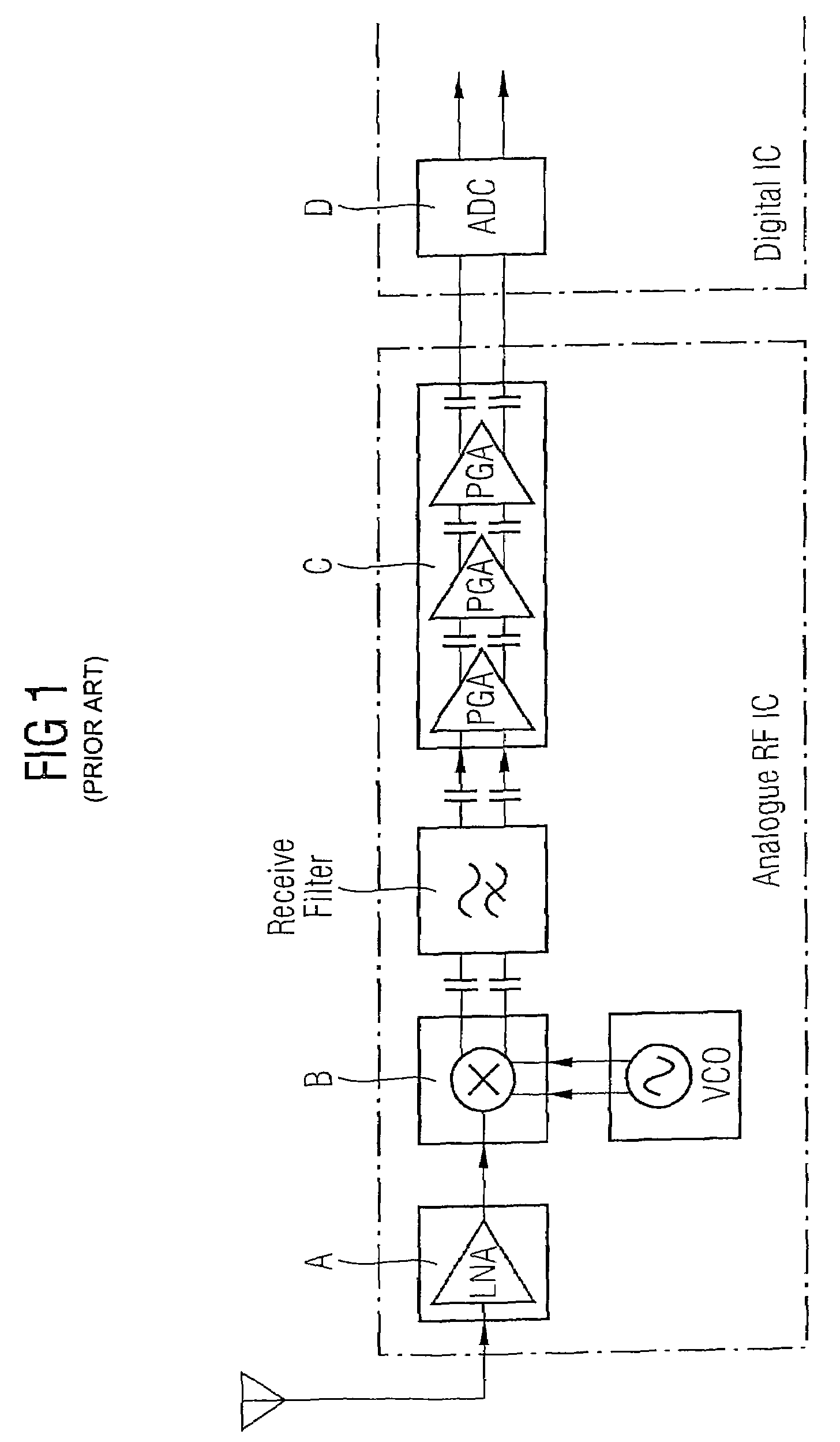
[0020]FIG. 1 is a prior art system that shows an example where each stage A, B, C will have some DC output, and switching of the programmable gain stages C (PGA) and the low noise amplifier A (LNA) would typically both change the DC output of the stage and would also change the amount of amplification of the DC output from the previous stages. This variable DC level, if not removed, requires increased headroom at the analogue to digital converter D, and can be difficult to remove in the digital circuitry. To avoid this, capacitors are inserted into the data path as shown in the figure. Together with the input resistance of the following stage, this forms a high-pass filter that completely removes DC components.

[0021]Typically, signals for wireless transmission are designed to have no DC component and thereby can be passed through an AC coupling chain. However, the signal may have significant low frequency components and it is therefore necessary to design an AC coupling with a corne...


PUM


Abstract

The present invention relates to receiver equipment with AC-coupled receiver circuits and AC coupling filters. A switch connected between a first stage and a second stage among the receiver circuits is adapted to switch from a high coupling corner frequency, for rapid settling of a signal during preparation of data reception, to a low corner frequency, for low signal distortion during data reception. The receiver circuits are adapted to use known properties in the signal to perform the switch at a time when the short term DC-components of the signal are as low as possible.

Description

REFERENCE TO RELATED APPLICATIONS[0001]This application is a continuation of PCT / EP2005 / 002622, filed on Mar. 11, 2005, which was not published in English, which claims the benefit of the priority date of German Patent Application No. EP 04 006 574.0, filed on Mar. 18, 2004.FIELD OF INVENTION[0002]The present invention relates to receiver equipment with AC-coupled receiver circuits, where it is desired to switch from a high coupling corner frequency for rapid settling during amplifier gain programming, for example, to a low corner frequency for low signal distortion during data reception. The present invention also relates to a method to switch from a high coupling corner frequency to a low corner frequency in receiver equipment with AC-coupled receiver circuits.BACKGROUND OF THE INVENTION[0003]It is desirable to use AC coupling between circuit stages e.g. amplifiers and mixers, in a receiver circuit in order to prevent unwanted DC signals caused by circuit DC bias voltages and mism...

Claims


Application Information

Patent Timeline
Patent Type & Authority Patents(United States)
IPC IPC(8): H03K9/00H04B1/06H04B7/00H04L27/06H04L27/08H03D3/00H04B1/30H04L25/06
CPCH03D3/008H04B1/30H04L25/06
Inventor LEWIS, MICHAELRUDBERG, MIKAELWAGNER, ELMAR
Owner INTEL CORP
Why Eureka
Try Eureka