Measuring methods for use on machine tools

a technology for measuring methods and machine tools, applied in the direction of wind musical instruments, programme control, instruments, etc., can solve the problems of inability to effectively use an analogue or scanning probe on a machine tool, limitations of commercially available machine tool controllers, and inability to use conventional machine tool controllers

Active Publication Date: 2009-04-28
RENISHAW PLC
View PDF15 Cites 23 Cited by
  • Summary
  • Abstract
  • Description
  • Claims
  • Application Information

AI Technical Summary

Benefits of technology

The invention allows for measuring data by combining data from a predetermined path with data from a probe output. This means that we don't have to get real-time data directly from the machine's servo feedback system which controls its movement.

Problems solved by technology

The technical problem addressed by this patent is how to perform precise measurements on worksites using machines tools without causing damage or errors during the process.

Method used


Image

  • Measuring methods for use on machine tools
  • Measuring methods for use on machine tools
  • Measuring methods for use on machine tools

Examples


Embodiment Construction

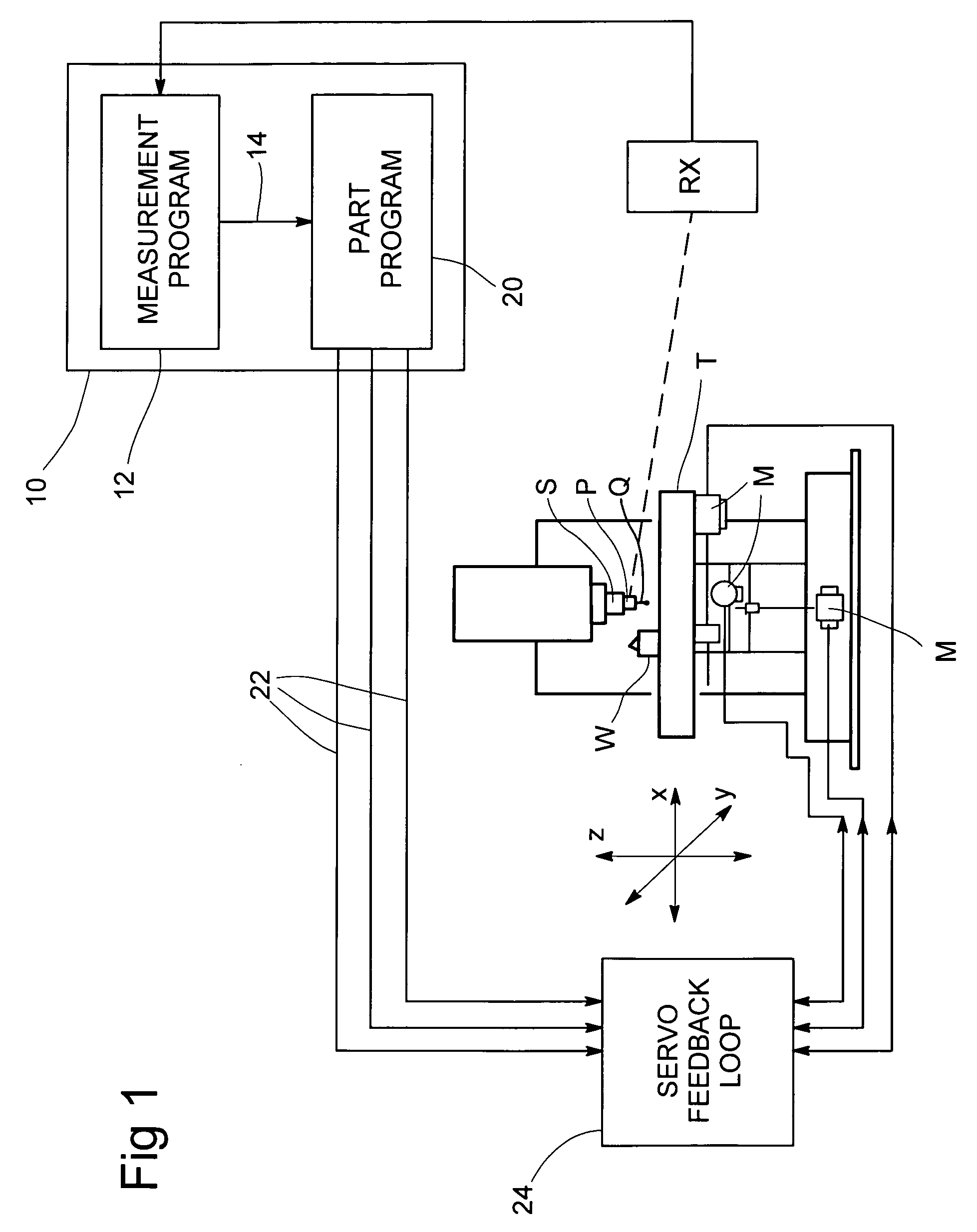
[0026]FIG. 1 shows a typical machine tool, comprising a table T and a spindle S which are movable relative to each other in directions x,y,z, under the action of motors M. As shown in this example, the motors M move the table, with the spindle remaining stationary. However, the invention is equally applicable to other machine tool arrangements, such as where the relative movement is produced between a stationary table or bed of the machine and a moving spindle.

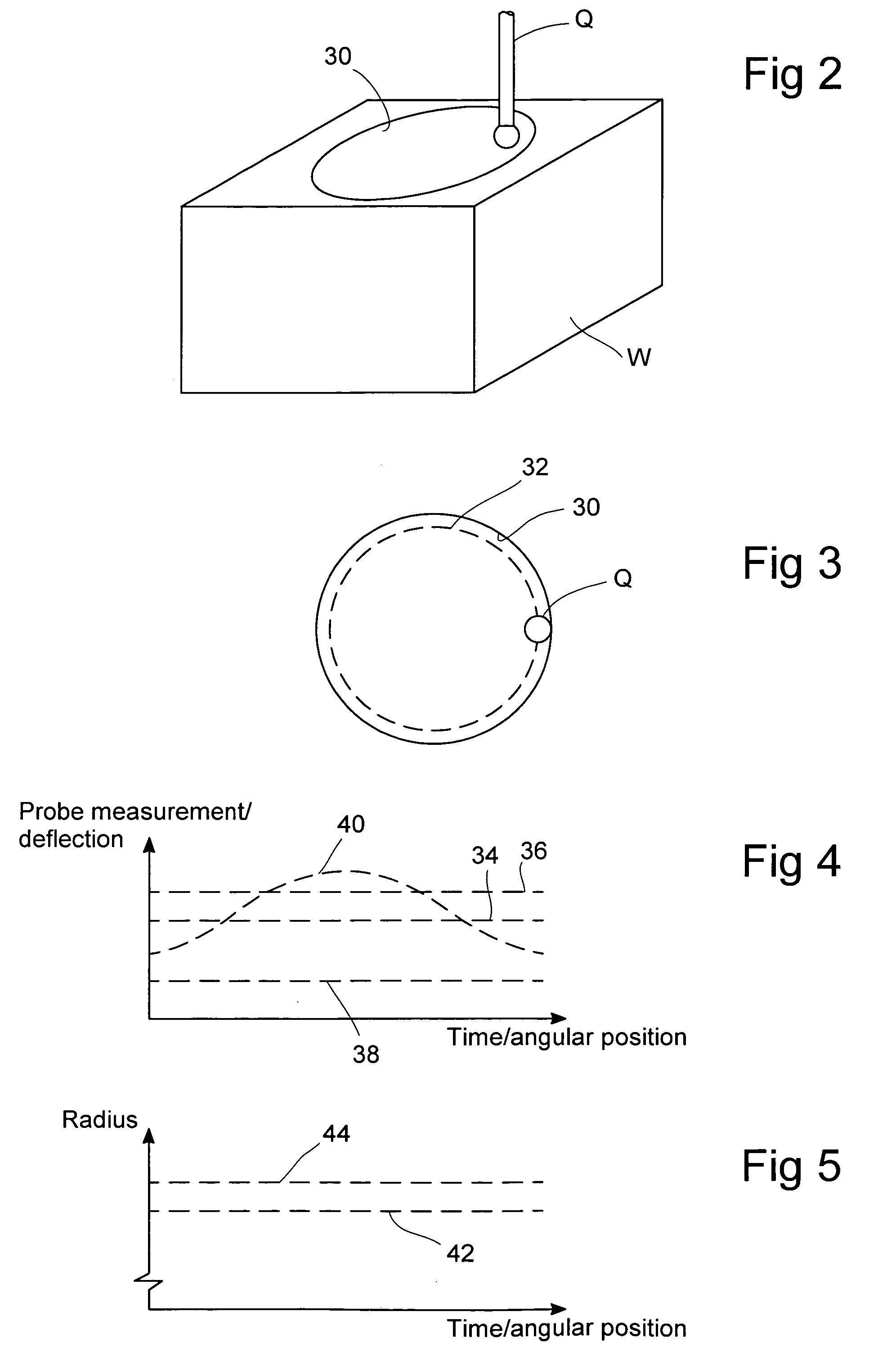
[0027]Normally, a cutting tool would be mounted in the spindle S, but FIG. 1 shows an analogue or scanning probe P mounted in the spindle instead, in order to perform scanning measurements on a workpiece W mounted on the table T. The probe P has a deflectable stylus Q for contacting the surface of the workpiece W, and transducers (not shown) in the probe P measure the deflection of the stylus Q in the directions x,y,z, e.g. as described in U.S. Pat. No. 4,084,323 (incorporated herein by reference).

[0028]The outputs of the prob...


PUM


Abstract

On a machine tool, a program receives data from a scanning or analogue probe, measuring a feature of a workpiece. This data is combined with assumed machine position data during the scanning movement. This avoids having to break into the servo feedback loop to get actual measured machine position data. The assumed machine position data can be derived from a part program which controls the scanning movement. Several ways are described for compensating for errors between the assumed machine position values and the actual values.

Description


Claims


Application Information

Patent Timeline
Owner RENISHAW PLC
Why Eureka
Try Eureka