
Indoor and outdoor unit communication via signal from a power line
a technology of indoor and outdoor units and power lines, applied in the field of control systems, can solve the problems of lowering the response rate, reducing the transmission rate and topology of the air conditioning system arranged to use the power line as transmission means, and so on, so as to save resources and install work
- Summary
- Abstract
- Description
- Claims
- Application Information
AI Technical Summary
Benefits of technology
Problems solved by technology
Method used
Image

Examples
first embodiment
[0024]the present invention will be described with reference to FIGS. 1 to 7.
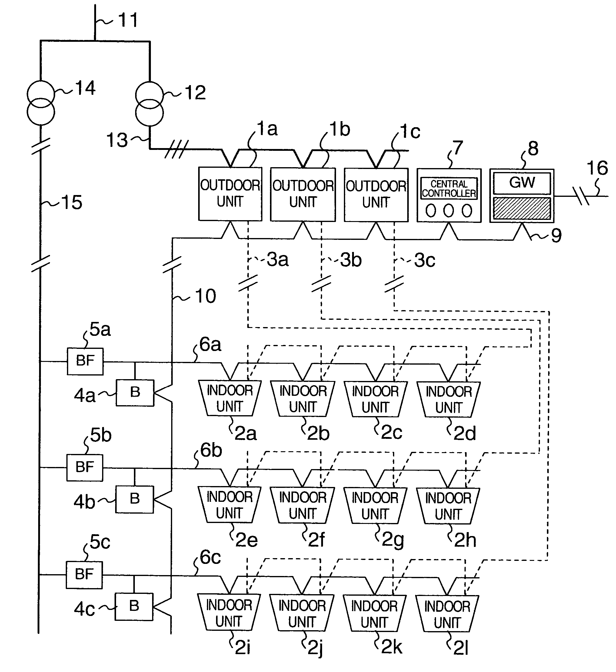
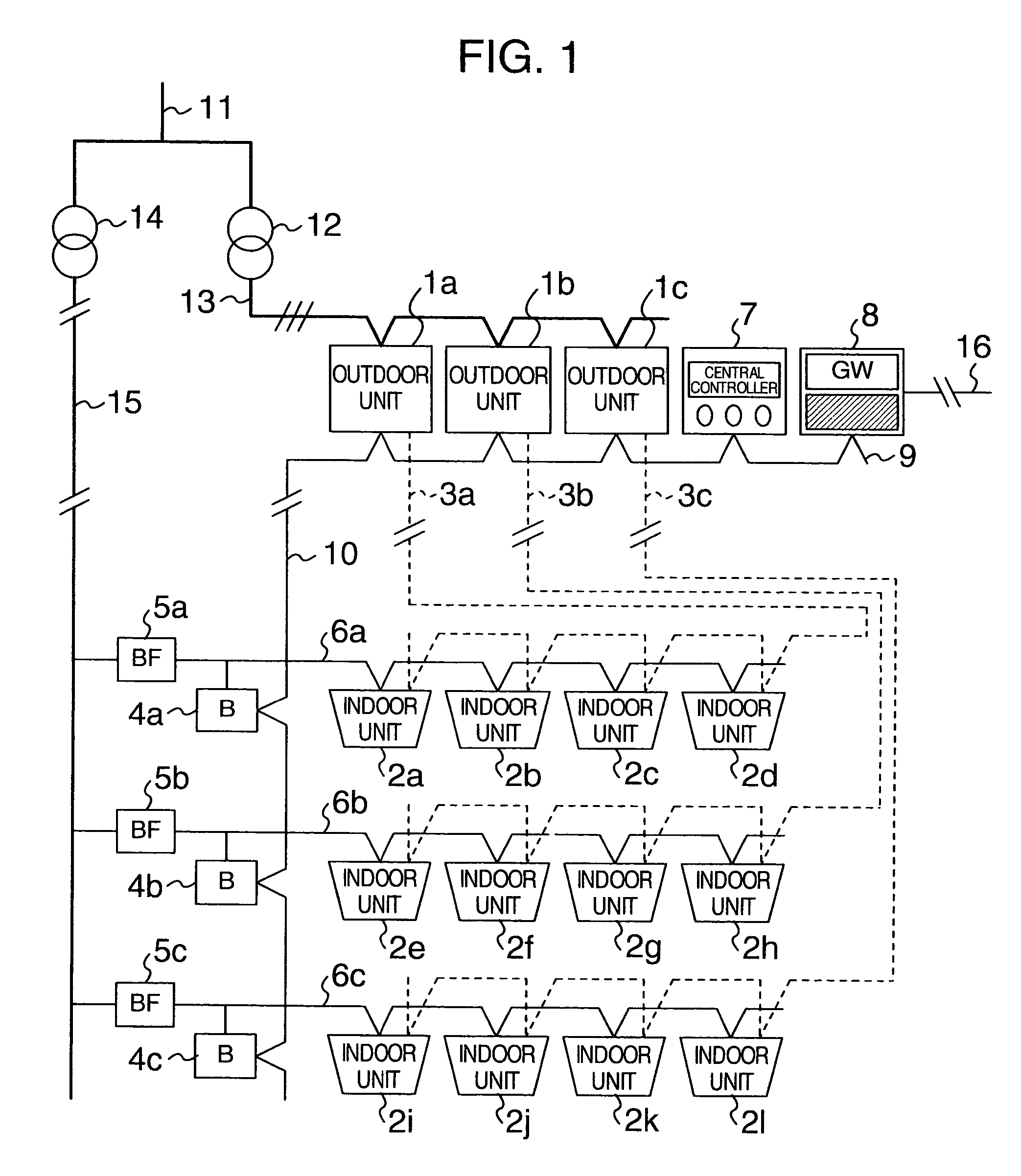
[0025]FIG. 1 is a schematic diagram showing an overall arrangement of an air conditioning system arranged to use a power line as a communication means according to the first embodiment of the present invention.
[0026]In FIG. 1, reference numbers 1a to 1c denote outdoor units, reference numbers 2a to 2l denote indoor units, reference numbers 3a to 3c denote refrigerant pipings, reference numbers 4a to 4c denote bridges, reference numbers 5a to 5c denote blocking filters, reference numbers 6a to 6c denote branch power lines, a reference number 7 denotes a central controller, a reference number 8 denotes a gateway, a reference number 9 denotes a transmission line through which data may be transmitted at high speed, a reference number 10 denotes a connecting wire between communication areas, a reference number 11 denotes a power-receiving line, a reference number 12 denotes a three-phase transformer, a reference...
second embodiment
[0056]In turn, the description will be oriented to the present invention with reference to FIGS. 8 to 11.
[0057]FIG. 8 is a schematic diagram showing an arrangement of an air conditioning system according to the second embodiment of the present invention. The different respect of the second embodiment from the first embodiment is a connection of the indoor units 500a to 500d through adapters 600a to 600d in addition to the connection of the indoor units 2a to 2h. Like the first embodiment, the second embodiment is equipped with the refrigerant piping, though it is not shown in FIG. 8.
[0058]Each of the indoor units 500a to 500d has the same arrangement as the conventional indoor unit. The indoor unit supplies the transmission data and the electric power through the effect of the adapter 600.
[0059]FIG. 9 is a schematic diagram showing an internal arrangement of the indoor unit 500 included in the second embodiment of the present invention. The indoor unit 500 corresponds to one of the ...
PUM
 Abstract
Description
Claims
Application Information