Adjustment device with a dual-guiding structure

a technology of guiding structure and adjustment device, which is applied in the direction of mechanical control device, gearing, instruments, etc., can solve the problems of limited technical aspects of conventional guiding adjustment device, time-consuming and cost-wasting guiding adjustment device, etc., and achieve the effect of convenient assembly for workers and convenient operation for users

Active Publication Date: 2009-09-08
CHERN SHING TOP
View PDF11 Cites 74 Cited by
  • Summary
  • Abstract
  • Description
  • Claims
  • Application Information

AI Technical Summary

Benefits of technology

[0007]The main objective of the present invention is to provide an adjustment device with a dual-guiding structure that is convenient in assembly for workers and in operation for users.

Problems solved by technology

A conventional wire-guiding adjustment device is limited in technical aspects and generally comprises a single guiding wheel that can be selectively arranged to receive one or two counter wound wires to synchronously operate the wires for changing the shape or position of the attached element such as the resilient backrest.
However, controlling the resilient backrest usually needs multiple sets of the wire-guiding adjustment devices.
Providing the resilient backrest with the wire-guiding adjustment devices is not only cost-wasting but also time-consuming, because it is hard to find proper locations and spaces for multiple sets which are neat in appearance and also not confusing in functions to users.

Method used


Image

  • Adjustment device with a dual-guiding structure
  • Adjustment device with a dual-guiding structure
  • Adjustment device with a dual-guiding structure

Examples


Embodiment Construction

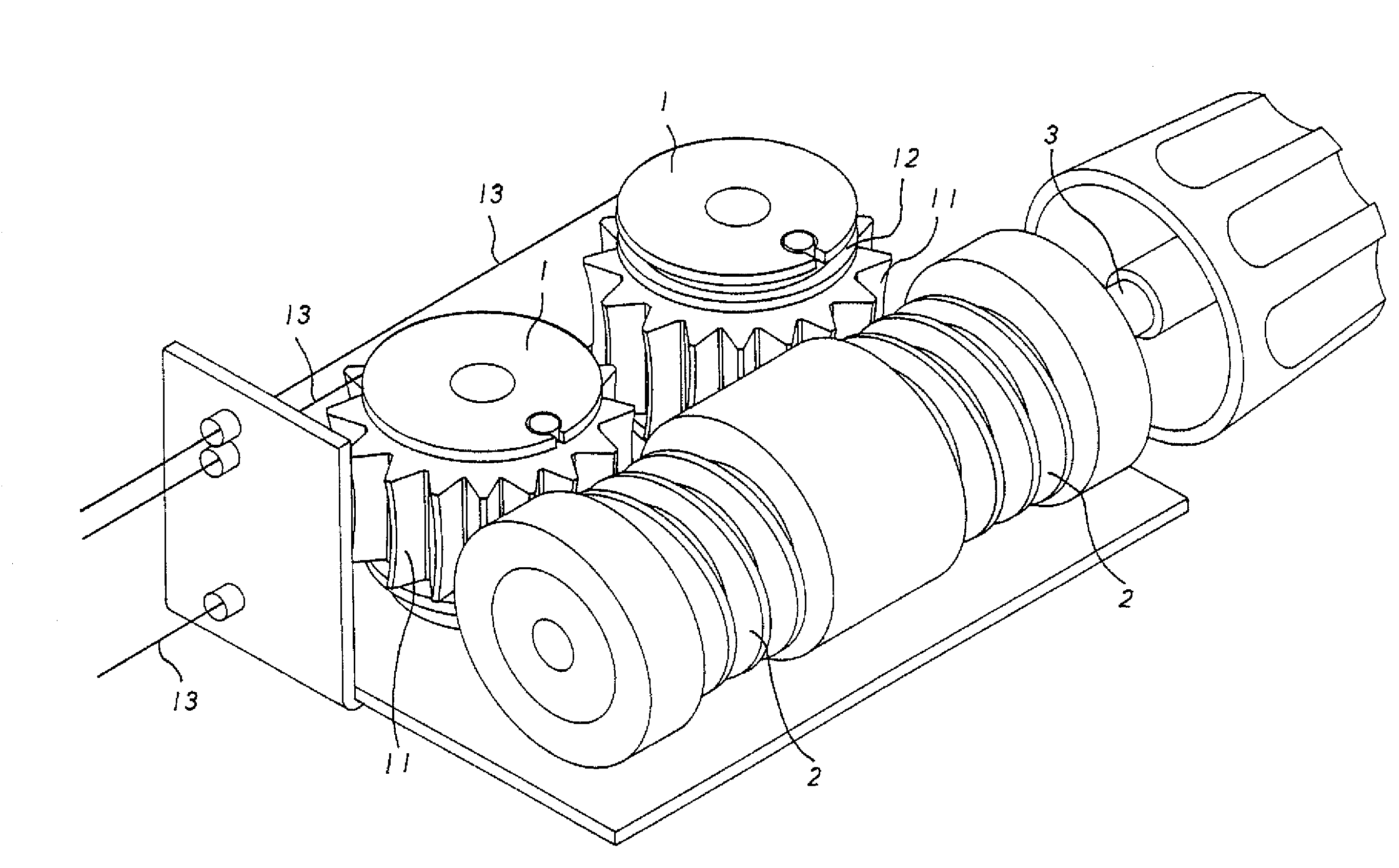
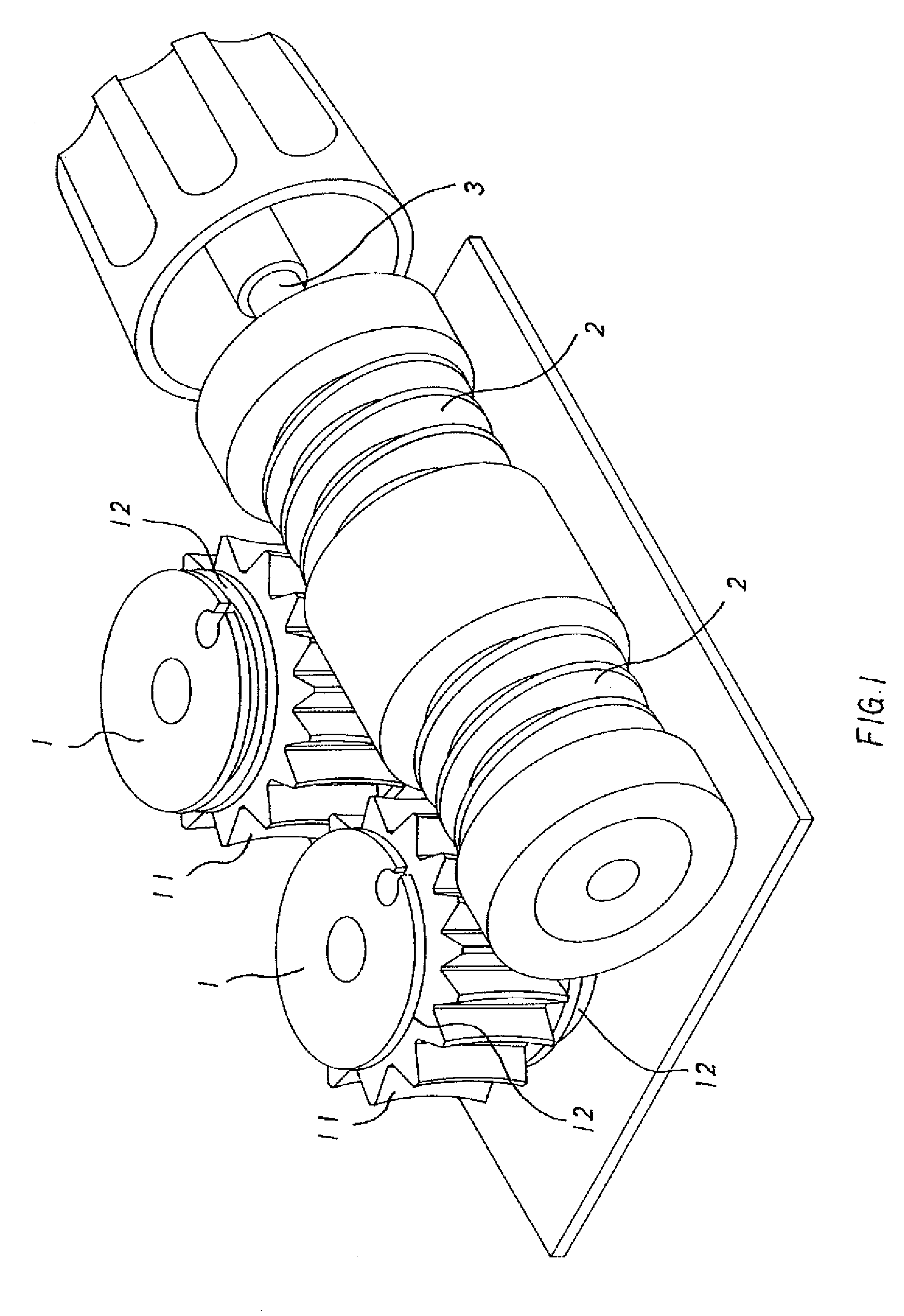
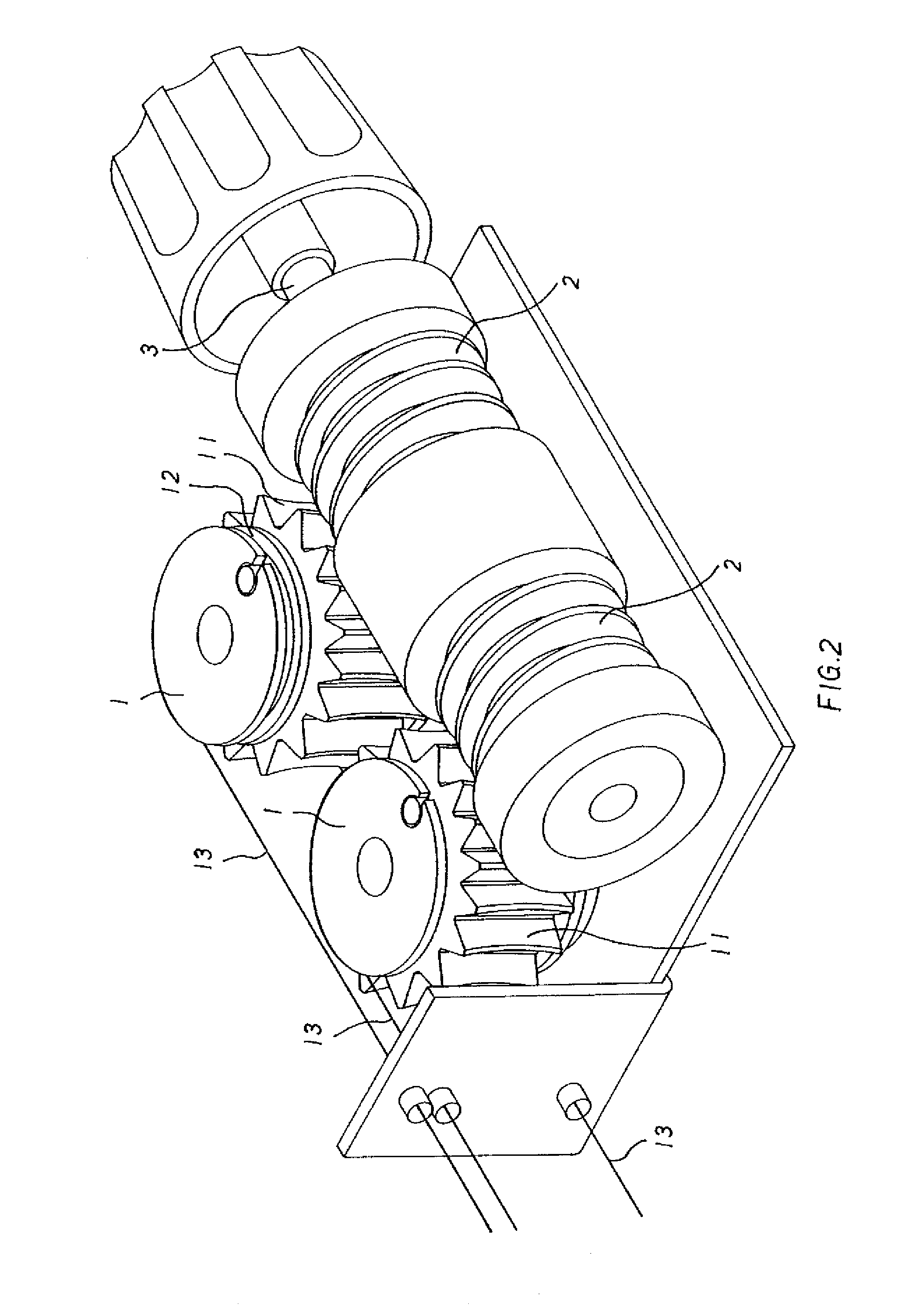
[0021]An adjustment device with a dual-guiding structure in accordance with the present invention has two worm wheels respectively meshed with two coaxial worm gears (the worm wheel and worm shaft structure is an application of gear and threaded shaft). Two worm gears are pivotally and axially fixed by a driving shaft. An adjacent end of each worm gear has a locking recess to receive a locking head mounted on the driving shaft. Thereby, the locking head is selectively engaged with the locking recess to drive the corresponding worm gear when the locking head on the driving shaft moves in reciprocation. Then, one worm wheel engaged with the corresponding worm gear is rotated to rewind or release the wires on the work wheel.

[0022]For more modification, the adjustment device selectively comprises at least two gears and at least two worn wheels respectively engaged with the worn gears so that the adjustment device receives multiple wires on the two worn wheels for multi-functional contro...


PUM


Abstract

An adjustment device with a dual-guiding structure has two worm wheels respectively meshed with two coaxial worm gears. The two worm gears are pivotally and longitudinally fixed by a driving shaft in line. An adjacent end of each worm gear has a locking recess to receive a locking head mounted on the driving shaft. Thereby, the locking head is selectively engaged with the locking recess of one of the worm gears to drive the corresponding worm gear when the locking head on the driving shaft is reciprocated. Then, one worm wheel engaged with the corresponding worm gear is rotated to rewind or release the wires on the work wheel.

Description

BACKGROUND OF THE INVENTION[0001]1. Field of the Invention[0002]The present invention relates to an adjustment device, and more particularly to an adjustment device composed of two worm gears coaxially combined together, two worm wheels respectively engaged with the two worm gears, and a shaft with a locking device.[0003]2. Description of Related Art[0004]A wire-guiding adjustment device is a structure for winding and releasing wires to vary positioning of an attached element by controlling the released length of the wires. For example, if an upper end and a lower end of a resilient backrest are controlled by the wires, the resilient backrest is bent into a big curved arc when the wires are wound to be shorter. On the other hand, when the wires are released to be longer, the resilient backrest rebounds to a straight shape. Therefore, the wire-guiding adjustment device has a wide application and various modifications in structures.[0005]A conventional wire-guiding adjustment device i...

Claims


Application Information

Patent Timeline
Patent Type & Authority Patents(United States)
IPC IPC(8): F16H1/16
CPCB60N2/0296G05G7/02B60N2/66Y10T74/19828
Inventor HSIAO, HSUEH-SHENG
Owner CHERN SHING TOP
Why Eureka
Try Eureka