Image-based visibility measurement

a technology of visibility measurement and image, applied in the field of measuring visibility, can solve the problems of reducing the light available to arrive from the target object, adding spurious light signatures, light absorption, etc., and achieve the effect of accurate measurement of visibility

Active Publication Date: 2009-10-13
INT ELECTRONICS MACHINES
View PDF5 Cites 42 Cited by
  • Summary
  • Abstract
  • Description
  • Claims
  • Application Information

AI Technical Summary

Benefits of technology

[0019]The invention provides an image-based visibility measurement solution in which an image is used to calculate a visibility (visual range). In one embodiment, a lighting condition for the image is determined and the visibility calculation is adjusted based on the lighting condition. Further, the invention can obtain image data for a set (one or more) of portions of the image and estimate a visual range based on each portion. The estimated visual ranges can be combined to calculate the visibility for the image. Still further, multiple metrics can be calculated, each of which is used to estimate a visual range. Subsequently, the visual ranges can be used to calculate the visibility for the image. Even further, configuration data that is based on a set of training images can be used to calculate the visibility for a new image. To this extent, the invention can incorporate the lighting condition, portions of an image having differing features, multiple metrics, and / or feedback through training images to accurately measure visibility based on an image.

Problems solved by technology

Light scattering contributes to extinction by scattering light from a target object out of the line of vision, thereby reducing the total incoming light from the target, and by scattering light from other directions into the line of vision, thereby adding spurious light signatures to those received from the target.
The second primary cause of extinction is light absorption, which reduces the light available to arrive from the target object, and is caused, for example, by other components of the atmosphere.
Historically, a lack of visibility, e.g., due to heavy rain, fog, snow, or the like, has contributed to more accidents in the various travel modalities, and particularly air travel, than virtually any other cause.
However, each of these solutions is limited.
For example, the transmissometer requires widely separated, precisely aligned components, and fails to account for extra light that is scattered into the field of view.
The nephelometer and scattered light meter do not measure the loss of light due to absorption, and the teleradiometer is limited to measuring the amount of light that arrives from the bearing of the target and is sensitive to non-uniform lighting and variations in inherent contrast.
However, even alone, these solutions are expensive, often large, and the results provided do not always accord with visual estimates provided by trained observers.
However, the measurements are based on the clarity of the air, and not the distance at which an individual can see a target object.
However, current video-based solutions are limited by requiring specialized and standardized target objects for measurement, require expensive, fragile equipment, provide variable results based on the time of day, lighting, and other factors, and require power consumption that makes deployment outside of an urban or suburban area questionable, if not impossible.
As a result, a single measurement of the extinction coefficient will fail to account for these differences.

Method used


Image

  • Image-based visibility measurement
  • Image-based visibility measurement
  • Image-based visibility measurement

Examples


Embodiment Construction

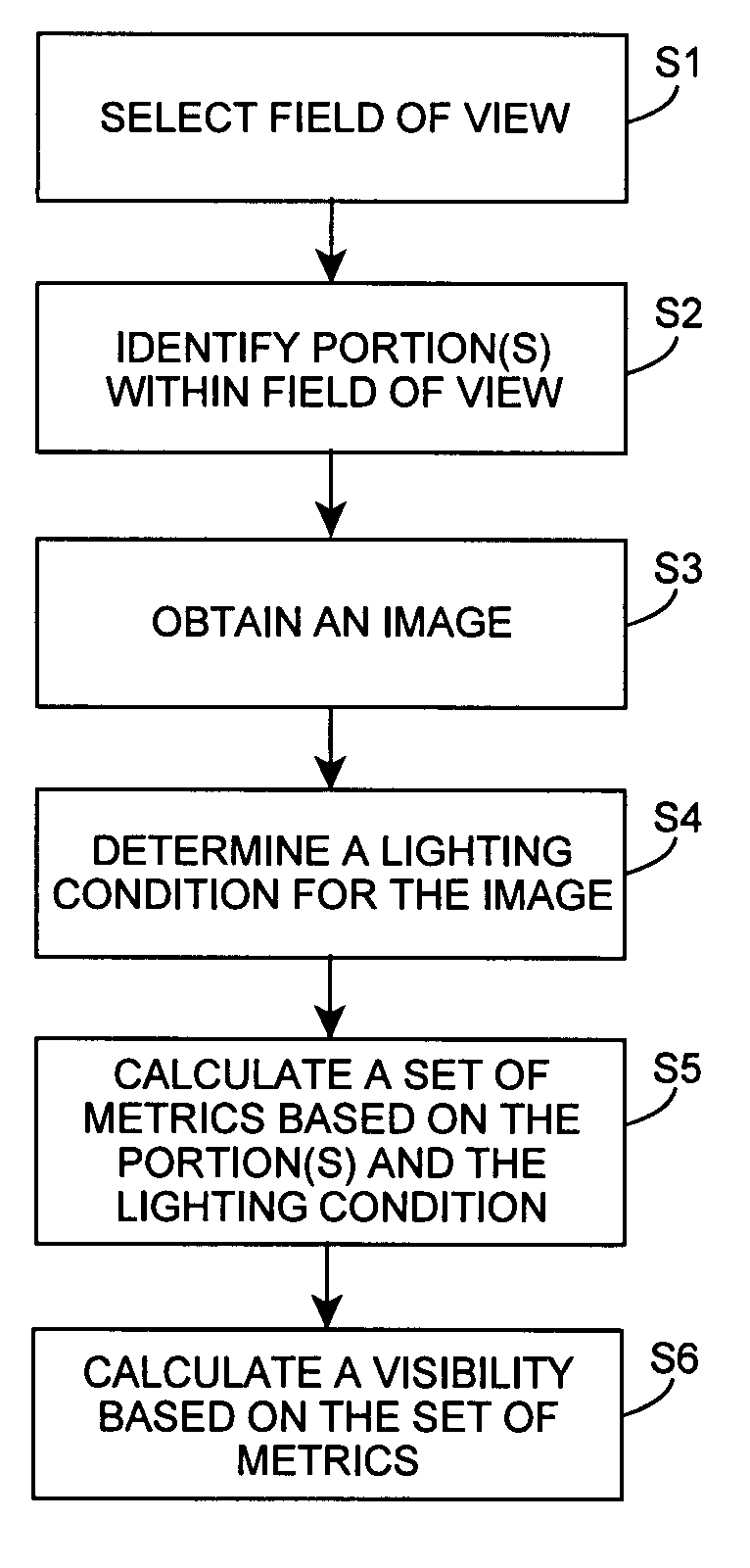
[0053]As indicated above, the invention provides an image-based visibility measurement solution in which an image is used to calculate a visibility (visual range). In one embodiment, a lighting condition for the image is determined and the visibility calculation is adjusted based on the lighting condition. Further, the invention can obtain image data for a set (one or more) of portions of the image and estimate a visual range based on each portion. The estimated visual ranges can be combined to calculate the visibility for the image. Still further, multiple metrics can be calculated, each of which is used to estimate a visual range. Subsequently, the visual ranges can be used to calculate the visibility for the image. Even further, configuration data that is based on a set of training images can be used to calculate the visibility for a new image. To this extent, the invention can incorporate the lighting condition, portions of the image having differing features, multiple metrics, ...


PUM

PropertyMeasurementUnit
field of viewaaaaaaaaaa
wavelengthaaaaaaaaaa
time periodaaaaaaaaaa

Abstract

The invention provides an image-based visibility measurement solution in which an image is used to calculate a visibility (visual range). In one embodiment, a lighting condition for the image is determined and the visibility calculation is adjusted based on the lighting condition. Further, the invention can obtain image data for a set of portions of the image and estimate a visual range based on each portion. The estimated visual ranges can be combined to calculate the visibility for the image. Still further, multiple metrics can be calculated, each of which is used to estimate a visual range. Subsequently, the visual ranges can be used to calculate the visibility for the image. Even further, configuration data that is based on a set of training images can be used to calculate the visibility for a new image. To this extent, the invention can incorporate the lighting condition, portions of the image having differing features, multiple metrics, and / or feedback through training images to accurately measure visibility based on an image.

Description

REFERENCE TO RELATED APPLICATION[0001]The current application claims the benefit of co-pending U.S. Provisional Application No. 60 / 577,590, filed on Jun. 8, 2004, which is hereby incorporated herein by reference.GOVERNMENT LICENSE RIGHTS[0002]The U.S. Government has a paid-up license in this invention and the right in limited circumstances to require the patent owner to license others on reasonable terms as provided for by the terms of Contract Number DG133R-03-CN-0069 awarded by the National Oceanic and Atmospheric Administration of the U.S. Department of Commerce.BACKGROUND OF THE INVENTION[0003]1. Technical Field[0004]The invention relates generally to measuring visibility, and more particularly, to an image-based solution for measuring visibility.[0005]2. Background Art[0006]Visibility, or visual range, is the distance at which a target object of a given size and characteristics can be seen. Knowledge of visibility is important for transportation, meteorological, and environment...

Claims


Application Information

Patent Timeline
Patent Type & Authority Patents(United States)
IPC IPC(8): G06K9/00G01N21/00G01N21/53G06T7/00
CPCG06T7/00G01N21/538
Inventor MIAN, ZAHID F.VONACHEN, WILLIAM G.
Owner INT ELECTRONICS MACHINES
Why Eureka
Try Eureka