Valve timing controller

a timing controller and valve technology, applied in the direction of gearing details, machines/engines, couplings, etc., can solve the problems of unavoidable clearance in the engagement boundary face between the first and second gear elements, and it is difficult for the second gear element to rattle to the first gear element, so as to prevent abnormal noise generation

Active Publication Date: 2009-10-20
DENSO CORP
View PDF3 Cites 15 Cited by
  • Summary
  • Abstract
  • Description
  • Claims
  • Application Information

AI Technical Summary

Benefits of technology

[0005]The present invention has been made in view of the foregoing problems and an object of the present invention is to provide a valve timing controller which restricts abnormal noises.
[0007]According to the above support arrangement of the second gear element, even if the changing torque is transmitted from the second, which is the other of the camshaft and the crankshaft, through the conversion portion to the second gear shaft, it is difficult for the second gear element to rattle to the first gear element. As a result, the tooth hit between the first and second gear elements due to the changing torque is avoided, thus preventing generation of abnormal noises.

Problems solved by technology

The second gear element forms a gear mechanism in an internal tooth engagement with the first gear element for performing a planetary motion, therefore unavoidably producing a clearance in the engagement boundary face between the first and second gear elements due to a manufacturing tolerance or the like.
According to the above support arrangement of the second gear element, even if the changing torque is transmitted from the second, which is the other of the camshaft and the crankshaft, through the conversion portion to the second gear shaft, it is difficult for the second gear element to rattle to the first gear element.

Method used


Image

  • Valve timing controller
  • Valve timing controller
  • Valve timing controller

Examples


first embodiment

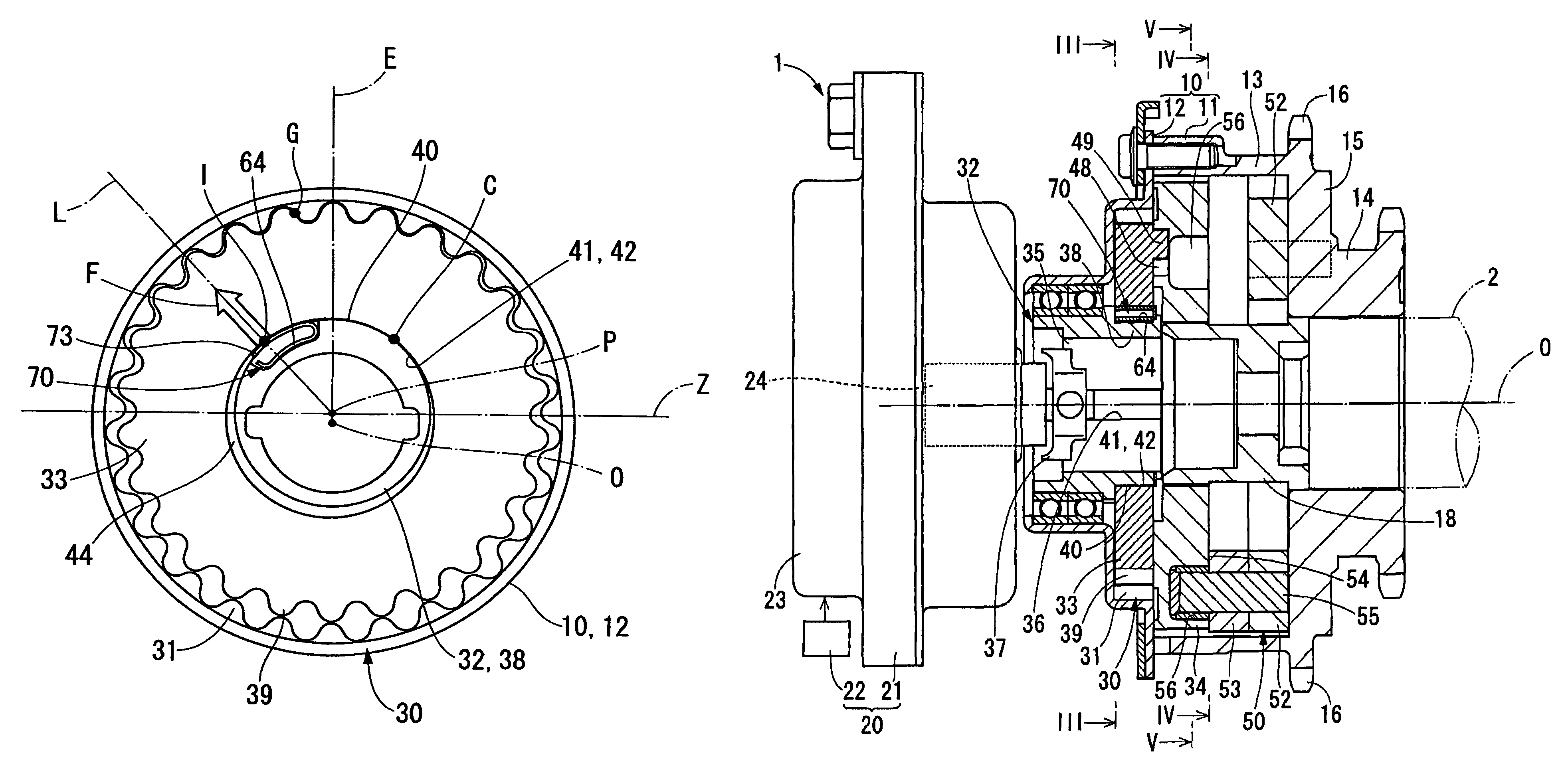
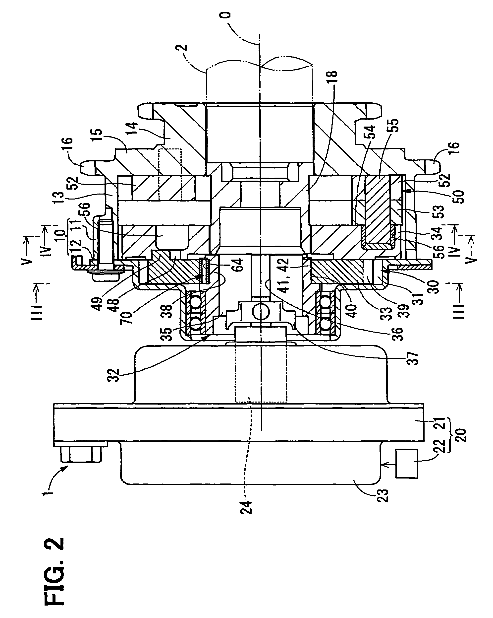
[0044]FIG. 2 shows a valve timing controller 1 in a first embodiment of the present invention. The valve timing controller 1 is provided in a transmission system for transmitting an engine torque from a crankshaft to a camshaft 2 for an internal combustion engine. The valve timing controller 1 changes a relative rotational phase of the camshaft to the crankshaft (hereinafter referred to as “engine shaft phase”) to adjust valve timing of an intake valve for the engine.

[0045]The valve timing controller 1 is provided with a drive-side rotational element 10, a driven-side rotational element 18, a control unit 20, a differential gear mechanism 30 and a link mechanism 50.

[0046]The drive-side rotational element 10 is formed in a hollow shape as a whole and receives the differential gear mechanism 30, the link mechanism 50 and the like therein. The drive-side rotational element 10 includes a two-shoulder cylindrical sprocket 11 and a two-shoulder cylindrical cover gear 12, a large diameter-...

second embodiment

[0076]As shown in FIGS. 9 and 10, a second embodiment of the present invention is a modification of the first embodiment.

[0077]In a differential gear mechanism 110 of a valve timing controller 100 in the second embodiment, a planetary bearing 120 is added between the gear inner peripheral surface 42 of the planetary gear 33 and the eccentric outer peripheral surface 40 of the eccentric cam portion 38. The planetary bearing 120 is a radial bearing holding ball-shaped rolling elements 123 between an outer ring 121 and an inner ring 122. An outer periphery 126 of the outer ring 121 is press-fitted into the gear inner peripheral surface 42 to rotate integrally with the planetary gear 33 and on the other hand, an inner peripheral surface 125 of a central bore 124 of the inner ring 122 is slidably and rotatably engaged with the eccentric outer peripheral surface 40. A clearance due to a manufacturing tolerance or the like is formed in the engagement boundary face between the inner periphe...

third embodiment

[0080]As shown in FIGS. 11A and 11B, a third embodiment of the present invention is a modification of the first embodiment.

[0081]In a differential gear mechanism 160 of a valve timing controller 150 in the third embodiment, a washer member 170 is added as a part of the planetary carrier 32 between the receiving portion 64 of the eccentric cam portion 38 and the spring member 70. The washer member 170 is made of a metallic sheet or the like and mostly has a circular cross section bent along the inner-peripheral-side contact portion 72 of the spring member 70 and the inner bottom face 66 of the receiving portion 64. A curvature radius Re, Rf of each of an inner peripheral surface 171 and an outer peripheral surface 172 of the washer member 170 is set to be smaller than a curvature radius Rb of the inner bottom surface 66 of the receiving portion 64 and larger than a curvature radius Ra of the inner-peripheral-side contact portion 72. Thereby, the inner peripheral surface 171 of the wa...


PUM


Abstract

A valve timing controller includes a first gear rotating together with a crankshaft, a planetary carrier eccentric to the first gear, a second gear engaging with the planetary carrier. The second gear performs a planetary motion while engaging with the first gear. The planetary motion is converted into a rotational motion of the camshaft to change a relative rotational phase between the crankshaft and the camshaft. A pressing element is provided between the planetary carrier and the second gear for pressing the second gear by the elastic force. An action line of the elastic force is inclined to the eccentric direction line of the planetary carrier in the circumferential direction.

Description

CROSS-REFERENCE TO RELATED APPLICATION[0001]This application is based on Japanese Patent Applications No. 2006-7361 filed on Jan. 16, 2006, No. 2006-193774 filed Jul. 14, 2006, and No. 2006-240365 filed on Sep. 5, 2006, the disclosure of which are incorporated herein by reference.FIELD OF THE INVENTION[0002]The present invention relates to a valve timing controller for an internal combustion engine which adjusts valve timing of at least one of an intake valve and an exhaust valve opened / closed by a camshaft on the basis of torque transmission from a crankshaft to the camshaft.BACKGROUND OF THE INVENTION[0003]There is conventionally known a valve timing controller which forces a planetary gear engaging with an internal gear rotating together with a crankshaft to perform a planetary motion for converting the planetary motion of the planetary gear into a motion of a camshaft, thereby changing a relative rotation phase between the camshaft and the crankshaft (for example, U.S. Pat. No. ...

Claims


Application Information

Patent Timeline
Patent Type & Authority Patents(United States)
IPC IPC(8): F01L1/34
CPCF01L1/352F01L2820/032F01L2820/02
Inventor SUGIURA, TAEIUEHAMA, MOTOKISUDOU, AKIYUKIMORII, YASUSHI
Owner DENSO CORP
Why Eureka
Try Eureka