
Reverse rotation preventing structure of centrifugal compressor

Inactive Publication Date: 2006-10-17
LG ELECTRONICS INC
View PDF17 Cites 5 Cited by
  • Summary
  • Abstract
  • Description
  • Claims
  • Application Information

AI Technical Summary

Benefits of technology

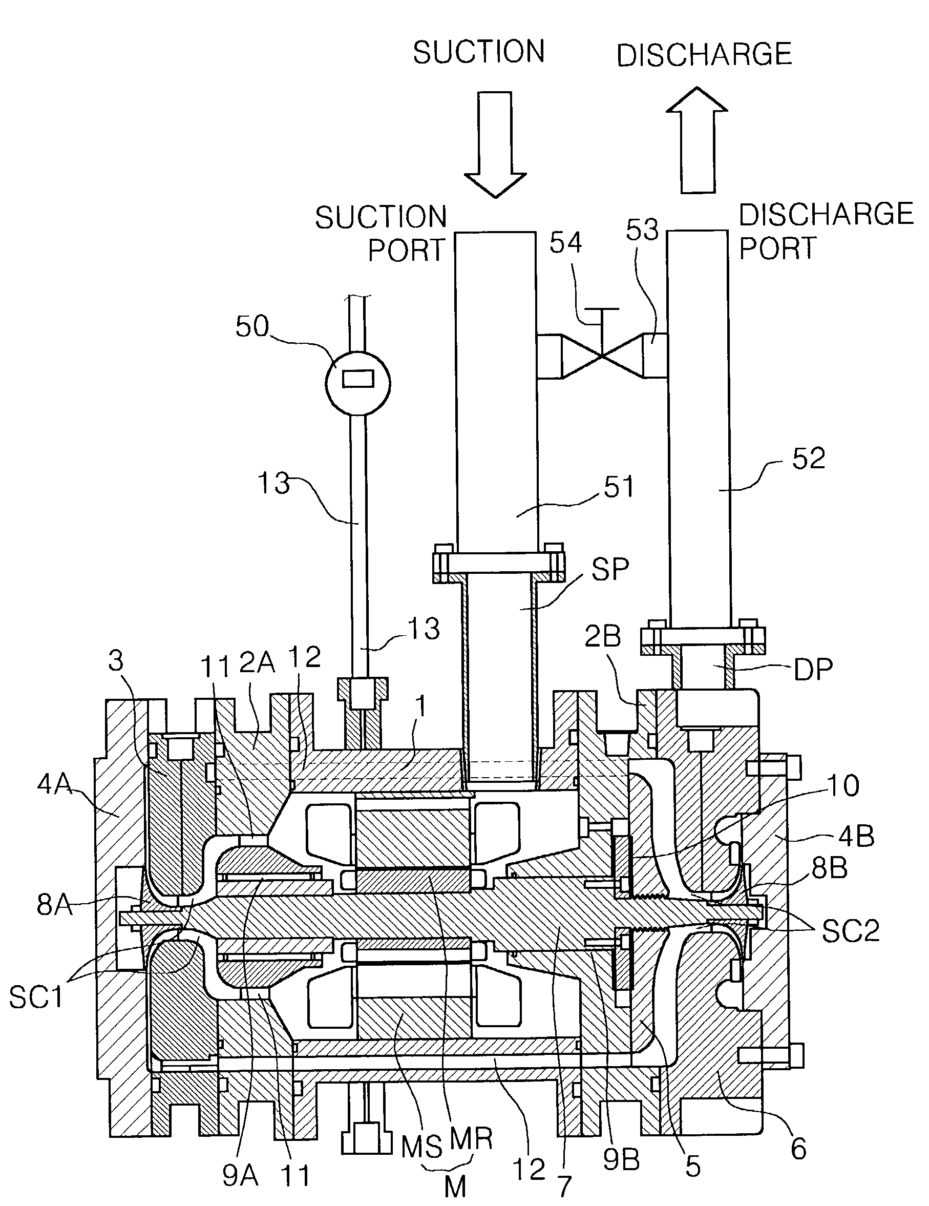
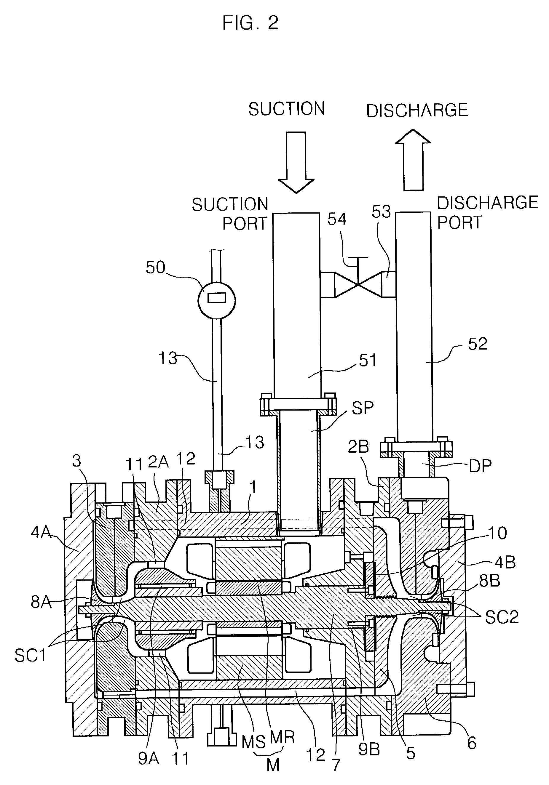
[0019]Accordingly the present invention has been devised to solve the foregoing problems of the prior art, and it is an object of the invention to provide a reverse rotation preventing structure of a centrifugal compressor, in which a stress that may cause an abnormal noise and a damage to parts of the centrifugal compressor at an emergency stop of the centrifugal compressor can be prevented by forming an additional path that can allow a fluid to be bypassed from a high-pressure side to a low-pressure side when an operation of the centrifugal compressor is suddenly stopped.
[0020]Further, it is another object of the present invention to improve a durability of the centrifugal compressor and an operational reliability thereof in the long run.
[0022]A reverse rotation preventing structure of a centrifugal compressor can prevent an abnormal noise and a damage to parts of the centrifugal compressor by reducing a reverse rotation of a rotating shaft and an abnormal flow of a refrigerant in the centrifugal compressor, which are caused by a backward flow of the refrigerant when an operation of the centrifugal compressor is suddenly stopped. Particularly, the present invention can prevent a dynamic-pressure air bearing for supporting a load of a rotating shaft from being damaged.

Problems solved by technology

However, there is an occasion that an operation of the compressor is suddenly stopped due to a power failure during the normal compression operation or a power shutdown caused by an abnormal operation of the centrifugal compressor.
Also, there is a problem that parts constituting the bearings 9A and 9B may be damaged.
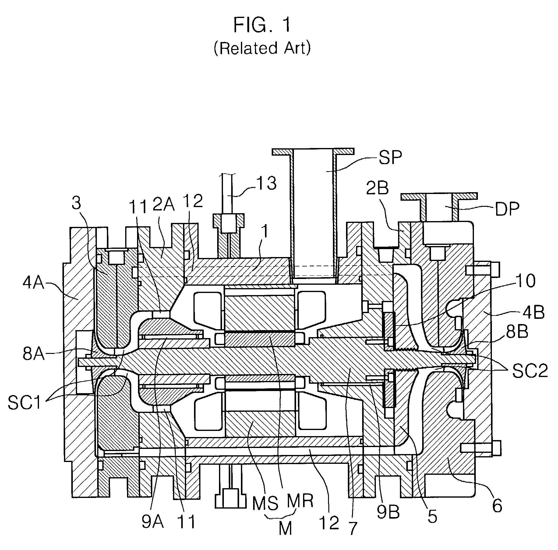
Further, there is a disadvantage that a severe noise occurs due to the abruptly backward flow of the refrigerant from the high-pressure discharge port DP to the low-pressure suction port SP when the operation of the centrifugal compressor is suddenly stopped.
Furthermore, an impulse occurring during the backward flow of the refrigerant as well as the damages to the parts result in a shortening of a durability of the centrifugal compressor.

Method used


Image

  • Reverse rotation preventing structure of centrifugal compressor
  • Reverse rotation preventing structure of centrifugal compressor
  • Reverse rotation preventing structure of centrifugal compressor

Examples


Embodiment Construction

[0029]Hereinafter, preferred embodiments relating with a reverse rotation preventing structure of a centrifugal compressor in accordance with the present invention are described in detail with reference to the accompanying drawings. The same reference numbers as the prior art will represent the same elements as the prior art.

[0030]FIG. 2 is a sectional view showing a reverse rotation preventing structure of a centrifugal compressor in accordance with the present invention.

[0031]Referring to FIG. 2, the reverse rotation preventing structure of the centrifugal compressor includes a structure for preventing a backward flow of a refrigerant from a discharge port DP to a suction port SP in case where an operation of the compressor is suddenly stopped due to a power failure or a power shutdown caused by an abnormal operation of the centrifugal compressor.

[0032]The reverse rotation preventing structure of the centrifugal compressor in accordance with the present invention includes a suctio...


PUM


Abstract

The invention relates to a reverse rotation preventing structure of a centrifugal compressor. The reverse rotation preventing structure of the centrifugal compressor comprises: a discharge pipeline of the centrifugal compressor; a suction pipeline of the centrifugal compressor; a bypass pipeline for connecting the discharge pipeline and the suction pipeline, wherein a predetermined valve is formed thereon; a control means for controlling an operation of the centrifugal compressor; and a detecting means for generating a predetermined signal to the control means if the operation of the centrifugal compressor is suddenly stopped, thereby opening the bypass pipeline.

Description

BACKGROUND OF THE INVENTION[0001]1. Field of the Invention[0002]The present invention relates to a centrifugal compressor, and more particularly, to a reverse rotation preventing structure of a centrifugal compressor, which is capable of preventing a reverse rotation in the compressor caused by a backward flow of a fluid due to a pressure difference between a suction side and a discharge side, when an operation of the compressor is suddenly stopped due to a power failure or a power shutdown caused by an abnormal operation of the compressor.[0003]2. Description of the Related Art[0004]Generally, a compressor is a machine that converts the mechanical energy into the compression energy of a compressive fluid, and is classified into a reciprocating type, a scroll type, a centrifugal (turbo) type and a vane (rotary) type.[0005]Among them, the centrifugal compressor (so-called turbo compressor) sucks a fluid in an axial direction using a rotation force of an impeller and then discharges t...

Claims


Application Information

Patent Timeline
IPC IPC(8): F04B49/03F04D17/10F04B49/10F04D27/00F04D27/02
CPCF04D27/0292F04D27/00
Inventor CHOI, MOON CHANGSUH, KWANG HAKIM, YOUNG KWANJI, YOO CHOLWANG, DAE SUNG
Owner LG ELECTRONICS INC
Learn More