Liquid droplet ejection head and image forming apparatus having the same

a technology of liquid droplet and image forming apparatus, which is applied in the direction of printing, inking apparatus, other printing apparatus, etc., can solve the problems of wasteful use of liquid (waste liquid), and achieve the effect of preventing evaporation of liquid, preventing the increase of viscosity of liquid, and preventing the increase of liquid viscosity

Inactive Publication Date: 2009-06-25
FUJIFILM BUSINESS INNOVATION CORP
View PDF6 Cites 59 Cited by
  • Summary
  • Abstract
  • Description
  • Claims
  • Application Information

AI Technical Summary

Benefits of technology

[0011]According to a second exemplary embodiment of the present invention, there is provided a liquid droplet ejection head comprising: an ejector including a nozzle for ejecting a liquid droplet, a pressure chamber communicating with the nozzle through a communication path, and an actuator for applying pressure to a liquid in the pressure chamber; a cap member for preventing evaporation of a liquid by capping the nozzle; a liquid viscosity-increase prevention structure for preventing an increase of viscosity of the liquid in the ejector; and a liquid viscosity-increase prevention controller for operating the liquid viscosity-increase prevention structure before the nozzle is uncapped from the cap member and ejects a liquid droplet.
[0012]According to a third exemplary embodiment of the present invention, there is provided an image forming apparatus having a liquid droplet ejection head, the liquid droplet ejection head comprising: an ejector including a nozzle for ejecting a liquid droplet, a pressure chamber communicating with the nozzle through a communication path, and an actuator for applying pressure to a liquid in the pressure chamber; a liquid viscosity-increase prevention structure for preventing an increase of viscosity of the liquid in the ejector; and a liquid viscosity-increase prevention controller for changing the operation frequency of the liquid viscosity-increase prevention structure when the liquid droplet is ejected from the nozzle, and when ejection of the liquid droplet is paused and no liquid droplet is being ejected from the nozzle.
[0013]According to a fourth exemplary embodiment of the present invention, there is provided an image forming apparatus having a liquid droplet ejection head, the liquid droplet ejection head comprises: an ejector including a nozzle for ejecting a liquid droplet, a pressure chamber communicating with the nozzle through a communication path, and an actuator for applying pressure to a liquid in the pressure chamber; a cap member for preventing evaporation of a liquid by capping the nozzle; a liquid viscosity-increase prevention structure for preventing an increase of viscosity of the liquid in the ejector; and a liquid viscosity-increase prevention controller for operating the liquid viscosity-increase prevention structure before the nozzle is uncapped from the cap member and ejects a liquid droplet.

Problems solved by technology

However, when the preliminary ejection is performed, a liquid is wastefully used (waste liquid) in no relation to image formation.

Method used


Image

  • Liquid droplet ejection head and image forming apparatus having the same
  • Liquid droplet ejection head and image forming apparatus having the same
  • Liquid droplet ejection head and image forming apparatus having the same

Examples


Embodiment Construction

[0033]An image forming apparatus, in which a liquid droplet ejection heads according to a first exemplary embodiment of the present invention is employed, will be explained using FIGS. 1 to 11.

[0034](Overall Arrangement)

[0035]As shown in FIG. 5, an inkjet recording apparatus 10 as an example of the image forming apparatus according to the invention includes a sheet feeding unit 12 in which sheet materials P as recording media are accommodated, an image recording unit 14 for recording an image to a sheet material P supplied from the sheet feeding unit 12, a transport means 16 for transporting the sheet material P to the image recording unit 14, and a sheet discharge unit 18 for accommodating the sheet material P to which the image is recorded by the image recording unit 14.

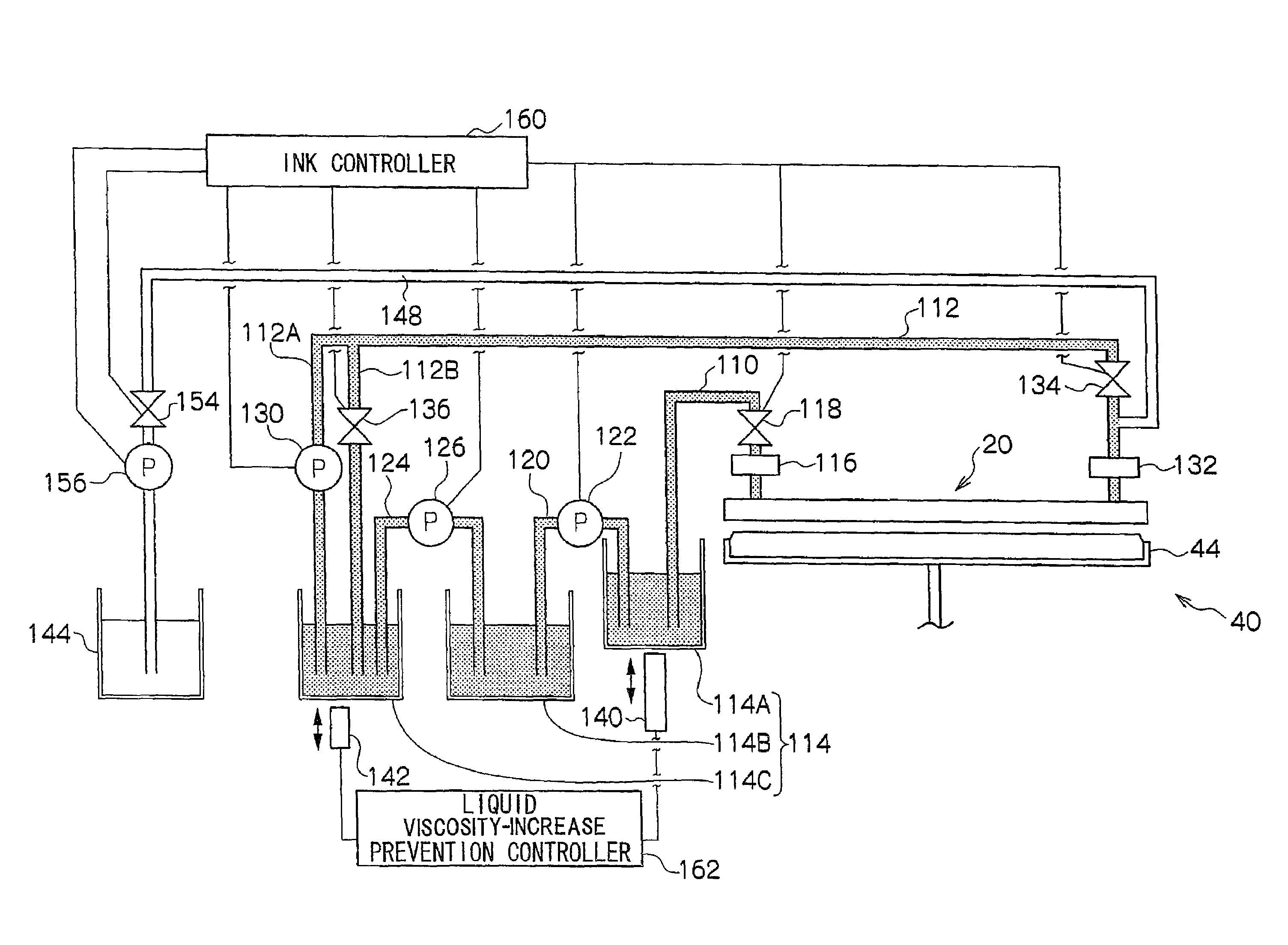
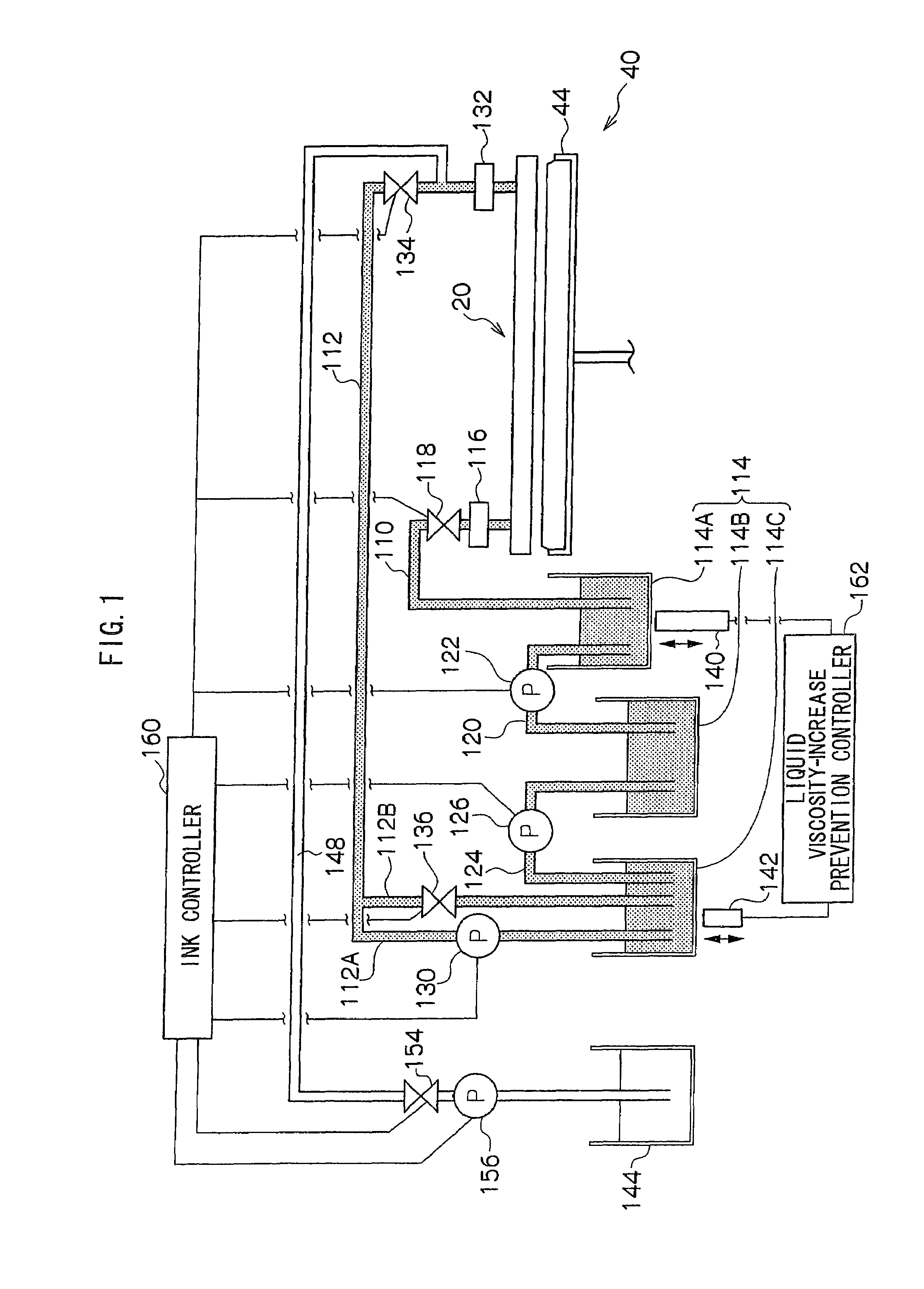
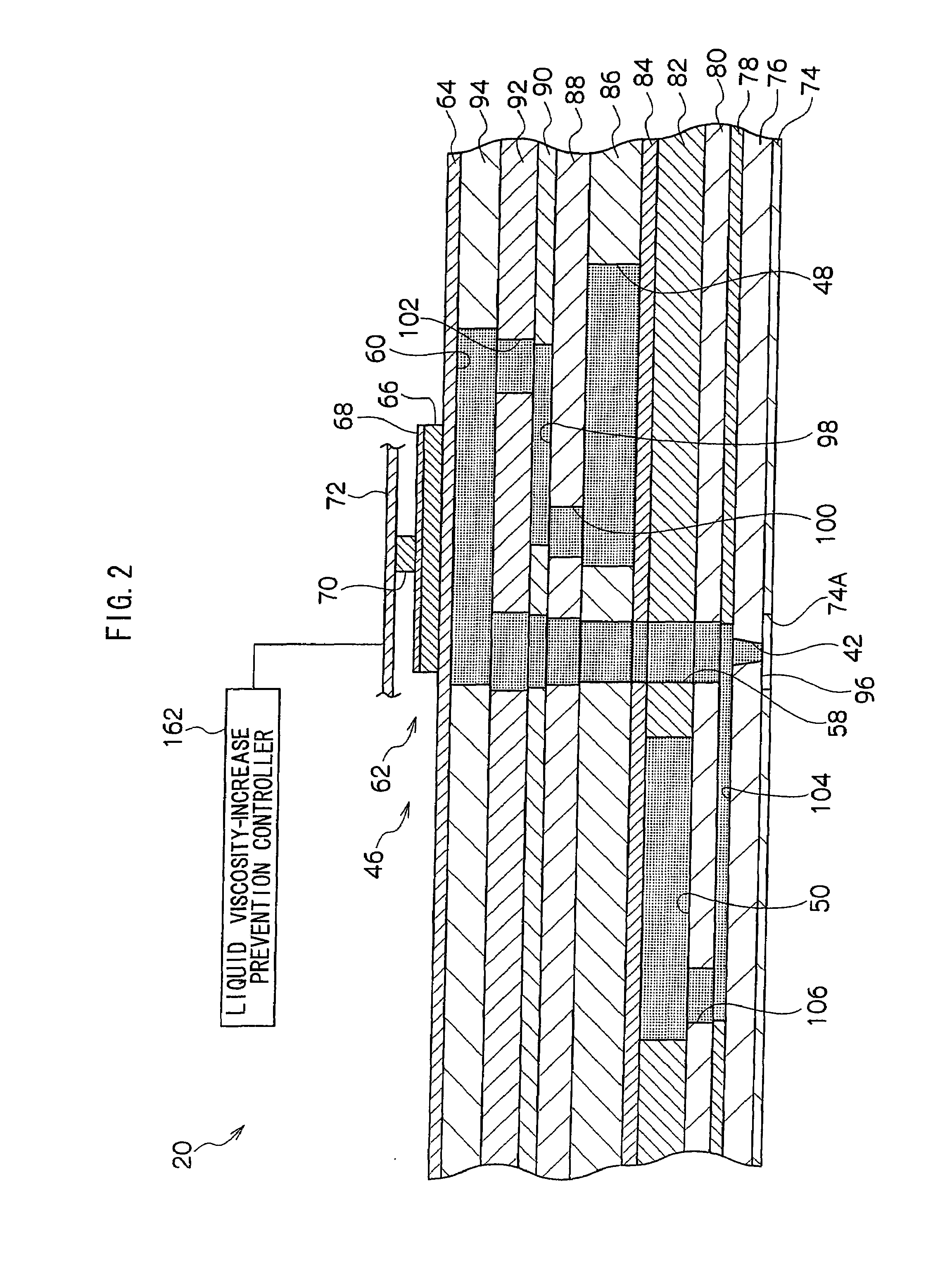
[0036]The image recording unit 14 has a liquid droplet ejection head 20. The liquid droplet ejection head 20 includes a nozzle surface 96 to which a multiplicity of nozzles 42 (refer to FIG. 2) are formed to eject ...


PUM


Abstract

A liquid droplet ejection head comprises an ejector, a liquid viscosity-increase prevention structure and a liquid viscosity-increase prevention controller. The ejector includes a nozzle for ejecting a liquid droplet, a pressure chamber communicating with the nozzle through a communication path, and an actuator for applying pressure to a liquid in the pressure chamber. The liquid viscosity-increase prevention structure prevents an increase of viscosity of the liquid in the ejector. The liquid viscosity-increase prevention controller changes the operation frequency of the liquid viscosity-increase prevention structure between when the liquid droplet is ejected from the nozzle and when ejection of the liquid droplet is paused and no liquid droplet is being ejected from the nozzle.

Description

CROSS-REFERENCE TO RELATED APPLICATION [0001]This application is based on and claims priority under 35 USC 119 from Japanese Patent Application No. 2007-332923 filed Dec. 25, 2007.BACKGROUND[0002]1. Technical Field[0003]The present invention relates to a liquid droplet ejection head for ejecting a liquid droplet and an image forming apparatus having the liquid droplet ejection head.[0004]2. Related Art[0005]There is known an image forming apparatus for ejecting a liquid droplet from a nozzle in a state that a liquid is circulated in an ejector to prevent the increase of viscosity of a liquid in the vicinity of the nozzle[0006]In more detail, when ejection of a liquid droplet is paused and no liquid droplet is being rejected from a nozzle, a liquid is also circulated in the same amount as that of the liquid circulating in an ejector when a liquid droplet is ejected from the nozzle. With this operation, the increase of viscosity of the liquid in the vicinity of the nozzle can be preve...

Claims


Application Information

Patent Timeline
Patent Type & Authority Applications(United States)
IPC IPC(8): B41J2/195
CPCB41J2/04581B41J2/04588B41J2/0459B41J2/04596B41J2/14233B41J2/16526B41J2202/12B41J2/175B41J2/17509B41J2/17596B41J2/18B41J2002/14419B41J2/16585
Inventor HAMAZAKI, TOSHINOBUHIRAKATA, SUSUMU
Owner FUJIFILM BUSINESS INNOVATION CORP
Why Eureka
Try Eureka