For this kind of image forming apparatus when a structural frame is composed of steel plate it is difficult to form a
complex formation.
However, while in this kind of configuration a structural frame made of steel plate is advantageous in terms of strength and resistance to deformation, unfortunately, due to the large number of parts, in addition to an increase in weight, time and labor required for
assembly is substantial, and manufacturing costs are increased.
Moreover, due to the large number of parts, dimensional errors increase due to part combining, and in order to implement accurate positioning retention a high degree of accuracy is required for each and every part.
In the case of color
copying machines, which can obtain multi-color images, the structure for a structural frame is especially complex.
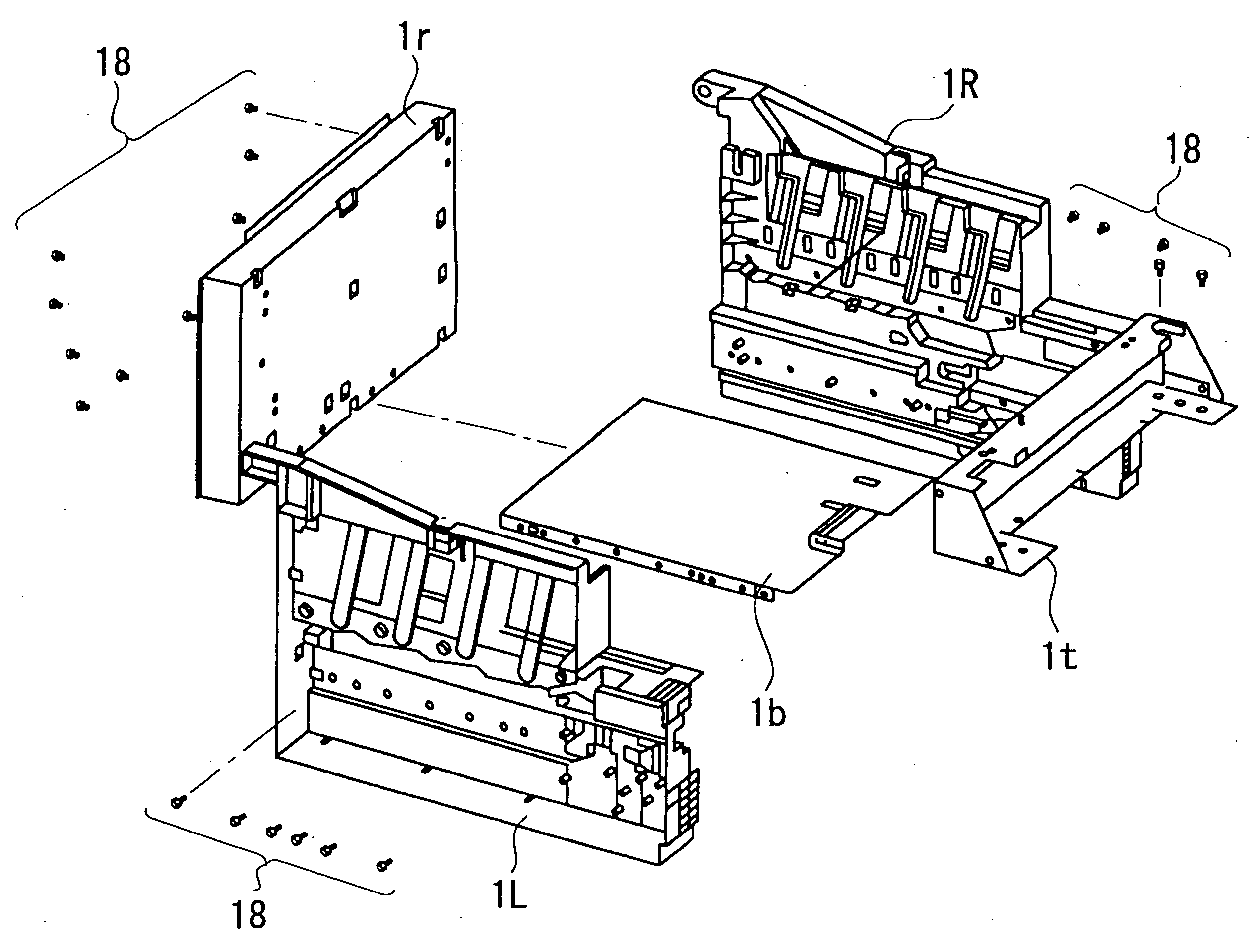
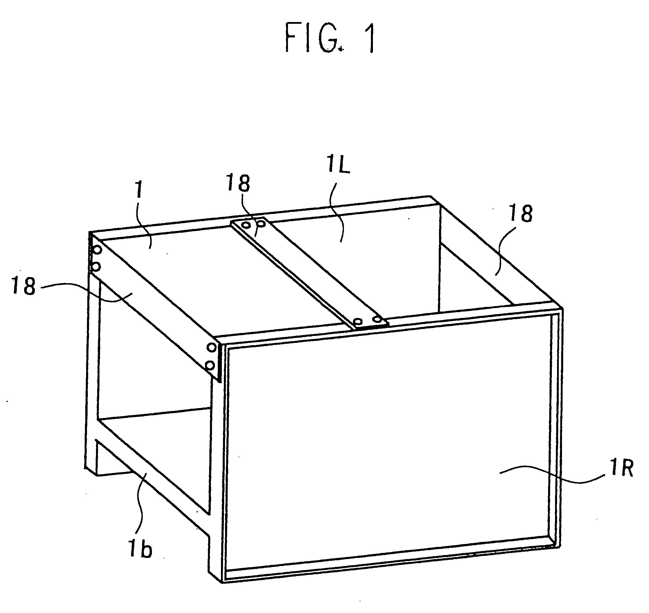
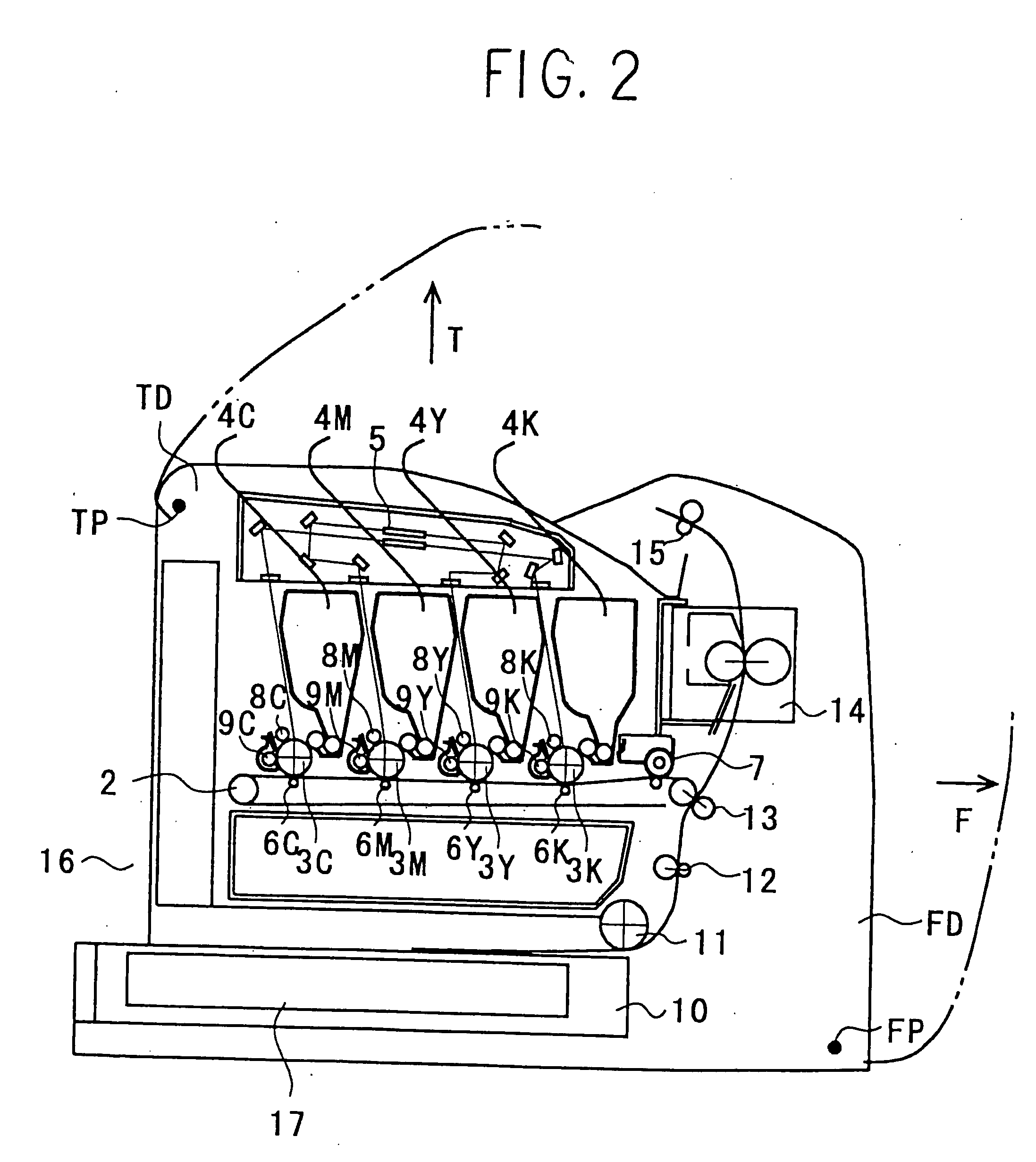
As a plurality of developing devices filled with different color toners, an intermediate transfer device and the like must be embedded in the structural frame, a large space is required inside the structural frame, and this makes it extremely difficult to ensure rigidity.
These aperture portions are a cause of rigidity degradation in the structural frame.
Moreover, as the releasing direction of a mold for resin molding used to form the structural frame is complex, the required degree of accurate positioning support becomes unobtainable.
Accuracy of the molded resin is easily obtained by using a mold having two simple releasing directions, as the structure of such a mold is uncomplicated.
However, the shapes that can be given to parts formed using such a mold are limited.
However, when used for continuous molding, the complex mold for this structure requires a longer than usual
cooling time.
As a result of this, often a longer amount of time is required than that which is ordinarily sufficient for the cooling and hardening of a melted resin.
Although by making part formations complex, the provision of various functions and reduction of manufacturing costs are aimed for, unfortunately, as a result of the lengthening of molding time, conversely costs are increased.
Accordingly, when an image forming apparatus structural frame is to be made from molded resin, as the degree of accuracy required is high, if the part formations are made too complex, the previously described mold also becomes complex, resulting in the required degree of accuracy being unobtainable.
Moreover, to obtain these part formations the time required for molding is lengthened and manufacturing costs cannot be lowered, resulting in a problem in terms of structural frame manufacturing costs.
Additionally, there is a problem from the point of view of mold manufacturing lead-time, as in order to give parts the required degree of accuracy, the time for completion of a mold of complex configuration is lengthy.
Furthermore, from the viewpoint of product development this means not being able to timely supply products the market is demanding.
This lengthening of the
development period in order to complete a mold of complex configuration is one of the most pressing issues the manufacturing industry faces.
However, the more compact and lightweight the main body of image forming apparatuses becomes, the higher the percentage of parts in which weight fluctuates during use, such as developing devices filled with toner, as well as recording medium such as paper and so on, and the higher the percentage of the amount of fluctuation of the center of gravity during use.
However, in the image forming apparatus, even if weight balance is taken into consideration and the respective printing devices, driving device, power supply and such are set such that weight is not locally focused, due to the above-described fluctuation of the center of gravity, weight focuses in specific positions and due to loss of balance of the reaction force added to the feet from the installation surface, the load focuses on a specific foot.
As a result of this, in a structural frame of a low rigidity using resin, deformation occurs and the degree of accuracy of positioning support is reduced, causing the generation of image defects.
These problems become more prominent the more compact and lightweight image forming apparatuses become.
However this kind of method cannot be employed as adverse effects such as increase in cost and weight are caused by the increase in material used.
However this kind of configuration is problematic in that, while the structural frame is integrally formed with resin, in addition to a large number of parts, and increase in weight, time and labor required for
assembly is substantial, and as a result manufacturing costs are increased.
However, due to the addition of the slide core the structure of the mold becomes complex, and as a result of the heat accumulation in the mold due to continuous molding as described previously, the required degree of accuracy cannot be obtained.
Moreover, if the
cooling time is lengthened in order to ensure accuracy, manufacturing costs are increased.
Furthermore, time for completion of a complex mold leads to a lengthening of the manufacturing
lead time and also results in an inability to timely provide products the market is demanding.
Consequently, for the realization of cost lowering of the image forming apparatus itself, the configuration of the structural frame is highly problematic from the
viewpoints of strength, accuracy and cost lowering.
However, as in a
color image forming apparatus having a tandem
system layering of colors takes place, the twisting of the main
body frame is problematic and directly results in color misalignment, and causes print quality to significantly deteriorate.
However, the above-mentioned method is problematic in that the number of parts of the image forming apparatus is large, and as such the cost of the mold and so on is increased.
Moreover, there are problems of assembly errors which occur when mounting positioning parts of the respective units on both steel plate side plates.

