System and method for stabilizing the human spine with a bone plate

a technology of bone plate and human spine, which is applied in the field of spine fixation system, can solve the problems of screw backout, risky fixation of bone plate to cervical spine, and risk to distal soft tissue structures

Inactive Publication Date: 2011-08-30
ZIMMER BIOMET SPINE INC
View PDF31 Cites 61 Cited by
  • Summary
  • Abstract
  • Description
  • Claims
  • Application Information

AI Technical Summary

Benefits of technology

[0010]In accordance with the present invention, a spinal plating system is provided that largely eliminates or reduces the aforementioned disadvantages of conventional spinal plating constructions. An embodiment of the invention relates to an implant system for fixation of the human spine that includes a plate having end boreholes, midline boreholes, screws, and expandable / contractible rings.
[0011]The end boreholes preferably extend from the upper surface to the lower surface of the plate. The end boreholes may be disposed in pairs at opposite ends of the plate. Each end borehole is preferably sized to receive at least a portion of a head of a screw therein. Each end borehole is also preferably spherical shaped to permit the screw to be “obliquely angulated” relative to the plate. Herein, “obliquely angulated” is taken to mean that the screw may be positioned at a wide range of angles relative to the plate, wherein the range of angles is preferably from 0 degrees to about 15 degrees from an imaginary axis that is perpendicular to the plate. Since the screws may be obliquely angulated with respect to the plate, the occurrence of screw backout from a bone may be significantly reduced.
[0012]The expandable / contractible rings are preferably sized so that they may be positioned within each borehole between the plate and each of the screw heads. The inner surface of each ring is preferably shaped to mate with a screw head while the outer surface is preferably shaped to mate with the plate. The outer surface of each screw head may be tapered such that an upper portion of the head is larger than a lower portion of the head. Each ring may also have a gap that extends vertically through the ring to render it expandable / contractible. Thus, during insertion of a screw head within a bone, the ring preferably exerts a compressive force on the screw head to fixably connect the screw to the plate. The screw may be prevented from contacting tissue structures that are protected by the spine even when screw backout occurs since the screw is attached to the plate.
[0014]Prior to surgical implantation of the spinal plate system, the expandable / contractible rings may be placed within the end boreholes of the plate. The plate may then be positioned adjacent to a portion of the spine that requires spinal fixation. Holes may be drilled and tapped into a portion of the bone underlying each end borehole at the desired angle. Screws may be inserted through the end boreholes into the holes, and the heads of the screws may be positioned within the boreholes such that the rings surround at least a portion of the heads. Advantageously, during insertion of the screws, the rings preferably lock the screws in place without occupying regions outside of the boreholes. Further, since the rings are pre-positioned within the end boreholes, surgeons do not have to worry that they may drop the rings during insertion of the screws.

Problems solved by technology

Spinal plate fixation to the cervical portion of the spine can be risky because complications during surgery can cause injury to vital organs, such as the brain stem or the spinal cord.
Bi-cortical screws are intended to breach the distal cortex for maximum anchorage into the bone; however, this may place distal soft tissue structures at risk.
Unfortunately, because of the soft texture of the bone marrow, the uni-cortical screws may undergo movement from their desired positions.
In fact, the portion of the bone surrounding such screws may fail to maintain the screws in their proper positions, resulting in screw backout.
Screw backout is particularly a problem when a pair of screws are implanted perpendicular to the plate.
When the screws are placed in such a manner, screw backout can occur as a result of bone failure over a region that is the size of the outer diameter of the screw threads.
Although positioning screws angled toward or away from each other in a bone reduces the risk of a screw backout, such backouts can still happen.
The result of a screw backout can be damaging to internal tissue structures such as the esophagus because a dislocated screw may penetrate the surface of such structures.
Unfortunately, breaches to the esophageal wall may permit bacterial contamination of surrounding tissues, including the critical nerves in and around the spinal cord, which can be fatal.
However, inserting the lock screw into and fixably positioning the lock screw within the opening may be difficult since the lock screw is very small.
The surgeon may be unable to hold onto the lock screw without dropping it.
Unfortunately, once such a tiny screw falls into the surgical wound, it may be unretrievable.

Method used


Image

  • System and method for stabilizing the human spine with a bone plate
  • System and method for stabilizing the human spine with a bone plate
  • System and method for stabilizing the human spine with a bone plate

Examples


Embodiment Construction

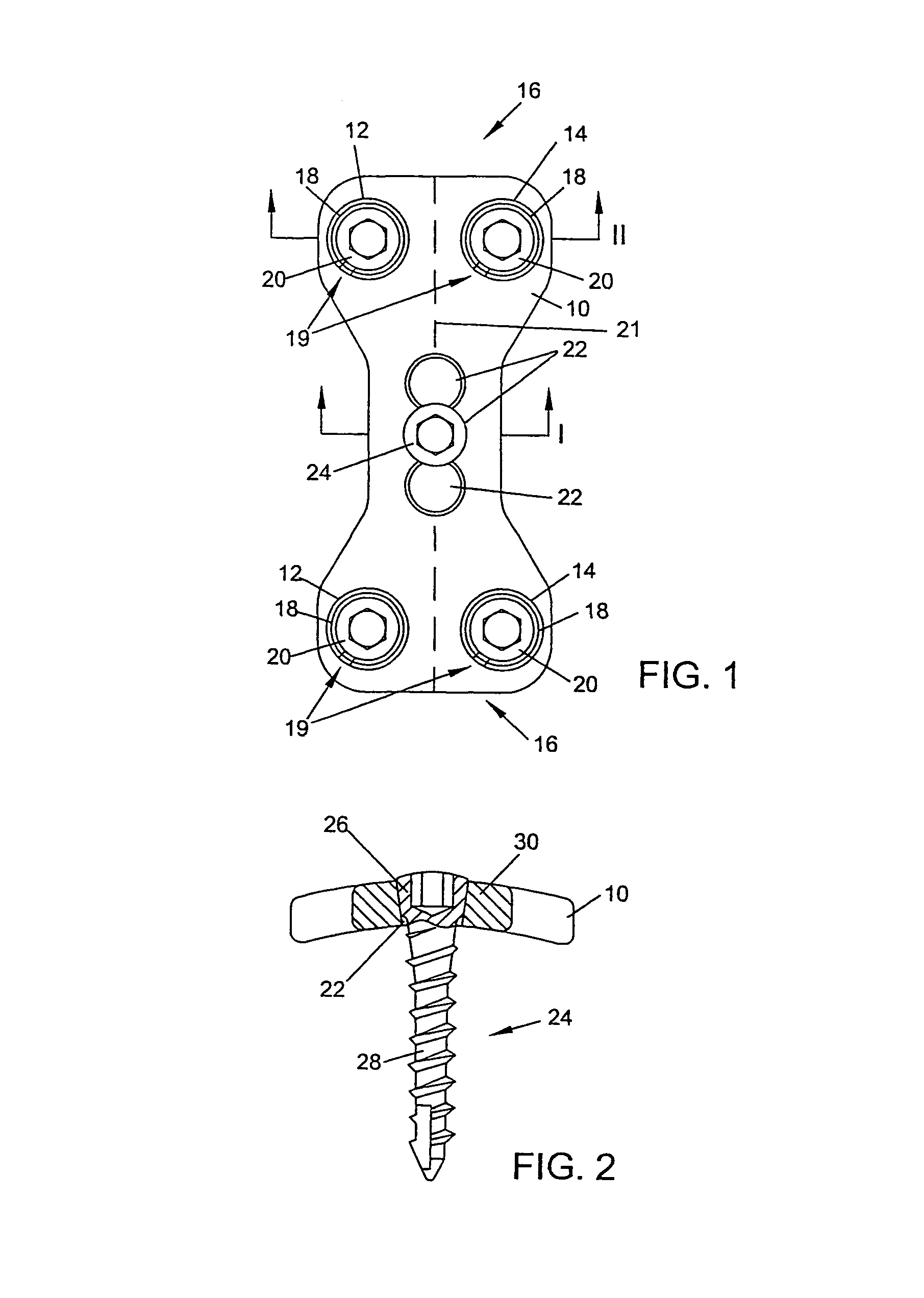
[0032]FIG. 1 depicts a top plan view of an embodiment of a spinal plating system. The spinal plating system may be used to correct problems in the lumbar and cervical portions of the spine. For example, the plating system may be implanted into the occiput bone which is located at the base of the skull. The plating system is preferably installed anterior to the spine. The spinal plating system preferably includes a plate 10 that may be placed adjacent to a portion of the spine. The length of plate 10 is preferably chosen so that the plate may span between at least two vertebrae. Plate 10 preferably includes a pair of end boreholes 12 and 14 located at opposite ends 16 of plate 10. End boreholes 12 and 14 are preferably formed vertically through plate 10 such that they extend from an upper surface to a lower surface of the plate. End boreholes 12 and 14 are preferably spaced from a longitudinal midline axis 21 of plate 10 by the same distance.

[0033]End boreholes 12 and 14 are preferab...


PUM


Abstract

A spinal plate system and method for fixation of the human spine is provided. In an embodiment, the system includes a bone plate, a bone screw and a ring. The bone screw preferably connects the bone plate to a bone, and the ring preferably fixes the bone screw into a borehole of the bone plate such that the bone screw extends from the bone plate at a selected angle. The ring is preferably capable of swiveling within the borehole to allow the bone screw to be angulated at a plurality of angles oblique to the plate. The bone screw may have a head having a tapered, threaded surface for engaging the ring. The ring preferably has threading on its inner surface for mating with the threading on the head. The inner surface of the ring may be tapered. Movement of the head through the ring preferably expands the ring against the bone plate to fix the bone screw at a selected angle relative to the bone plate.

Description

CROSS REFERENCE TO RELATED APPLICATIONS[0001]The present application is a continuation of U.S. patent application Ser. No. 10 / 036,012, filed Dec. 26, 2001 now abandoned; which is a continuation of U.S. patent application Ser. No. 09 / 089,027 filed Jun. 2, 1998, now U.S. Pat. No. 6,454,769; which is a continuation-in-part U.S. patent application Ser. No. 08 / 905,823, filed Aug. 4, 1997, now abandoned.BACKGROUND OF THE INVENTION[0002]1. Field of the Invention[0003]The present invention generally relates to spinal fixation systems and the like. More particularly, the present invention relates to a spinal plate system includes a mechanism for fixably attaching screws to a plate at a selected angle determined according to the patient's anatomy.[0004]2. Description of Related Art[0005]The use of spinal fixation plates for correction of spinal deformities and for fusion of vertebrae is well known. Typically, a rigid plate is positioned to span bones or bone segments that need to be immobiliz...

Claims


Application Information

Patent Timeline
Patent Type & Authority Patents(United States)
IPC IPC(8): A61B17/80A61B17/70A61B17/88
CPCA61B17/7059A61B17/8047A61B17/8052A61B17/8057
Inventor WAGNER, ERIK J.JONES, ROBERT J
Owner ZIMMER BIOMET SPINE INC
Why Eureka
Try Eureka