Operation method of nuclear power plant

a nuclear power plant and operation method technology, applied in nuclear power plant control, nuclear reactors, greenhouse gas reduction, etc., can solve the problems of increased pressure loss in the water-steam two-phase flow section, and large decrease of the average void rate in the cor

Active Publication Date: 2009-11-10
HITACHI-GE NUCLEAR ENERGY LTD
View PDF8 Cites 16 Cited by
  • Summary
  • Abstract
  • Description
  • Claims
  • Application Information

AI Technical Summary

Benefits of technology

[0006]When the above-mentioned related art is applied to the existing nuclear power plant, the rate of core flow passing through a reactor core is substantially the same as that before the power uprate, while thermal power of the core is increased. In a boiling water reactor (BWR), therefore, an average void rate (proportion of steam with respect to the channel volume) in the core is increased. Accordingly, the flow speed of a coolant is increased and so is a pressure loss in the core. Also, with an increase in the amount of steam generated in the core, a pressure loss in a water-steam two-phase flow section is increased and a margin of core safety tends to reduce. Further, an increase of the average void rate in the core increases an amount of steam condensed in the so-called pressure transient state where pressure rises, for example, when a generator load is cut off, thus resulting in a larger amount of decrease of the average void rate in the core. Generally, the boiling water reactor has a negative void feedback coefficient so that the reactor power reduces as the void rate increases. In the pressure transient state, however, the average void rate in the core is reduced and the reactor power is increased. Thus, the related art has a possibility that, after the power uprate, the amount of decrease of the average void rate in the core is increased in the pressure transient state and a design margin for pressure transient events is reduced.
[0008]An object of the present invention is to provide an operation method of a nuclear power plant, which can uprate plant power without greatly modifying the construction of plant equipment, while keeping a core's pressure loss characteristic, a safety margin, and a design margin in the transient state substantially the same as those before the power uprate.
[0017]Since the feedwater temperature can be adjusted to a set value through control of the opening of the extracted flow control valve, it is possible to suppress variations in the amount of power generated during the power uprate operation of the nuclear power plant.

Problems solved by technology

Also, with an increase in the amount of steam generated in the core, a pressure loss in a water-steam two-phase flow section is increased and a margin of core safety tends to reduce.
Further, an increase of the average void rate in the core increases an amount of steam condensed in the so-called pressure transient state where pressure rises, for example, when a generator load is cut off, thus resulting in a larger amount of decrease of the average void rate in the core.
In a usual nuclear power plant employing a boiling water reactor, the high pressure turbine is one of the equipment with a possibility that the design margin is first lost with the increase in the flow rate of main steam.
Also, in a nuclear power system other than the boiling water reactor, a similar problem arises in a plant where the design margin for the high pressure turbine is relatively small.
However, such a solution is not realistic for the reason that, if the flow rate of steam extracted for heating the feedwater is simply reduced as a whole, thermal efficiency is noticeably deteriorated and the electric power is not increased in proportion to the core thermal power output.

Method used


Image

  • Operation method of nuclear power plant
  • Operation method of nuclear power plant
  • Operation method of nuclear power plant

Examples


first embodiment

[0041]A first embodiment represents the case where the present invention is applied to a boiling water reactor system as one of nuclear power plants.

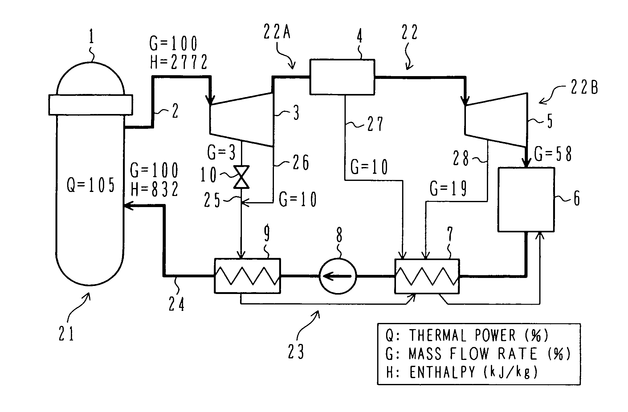
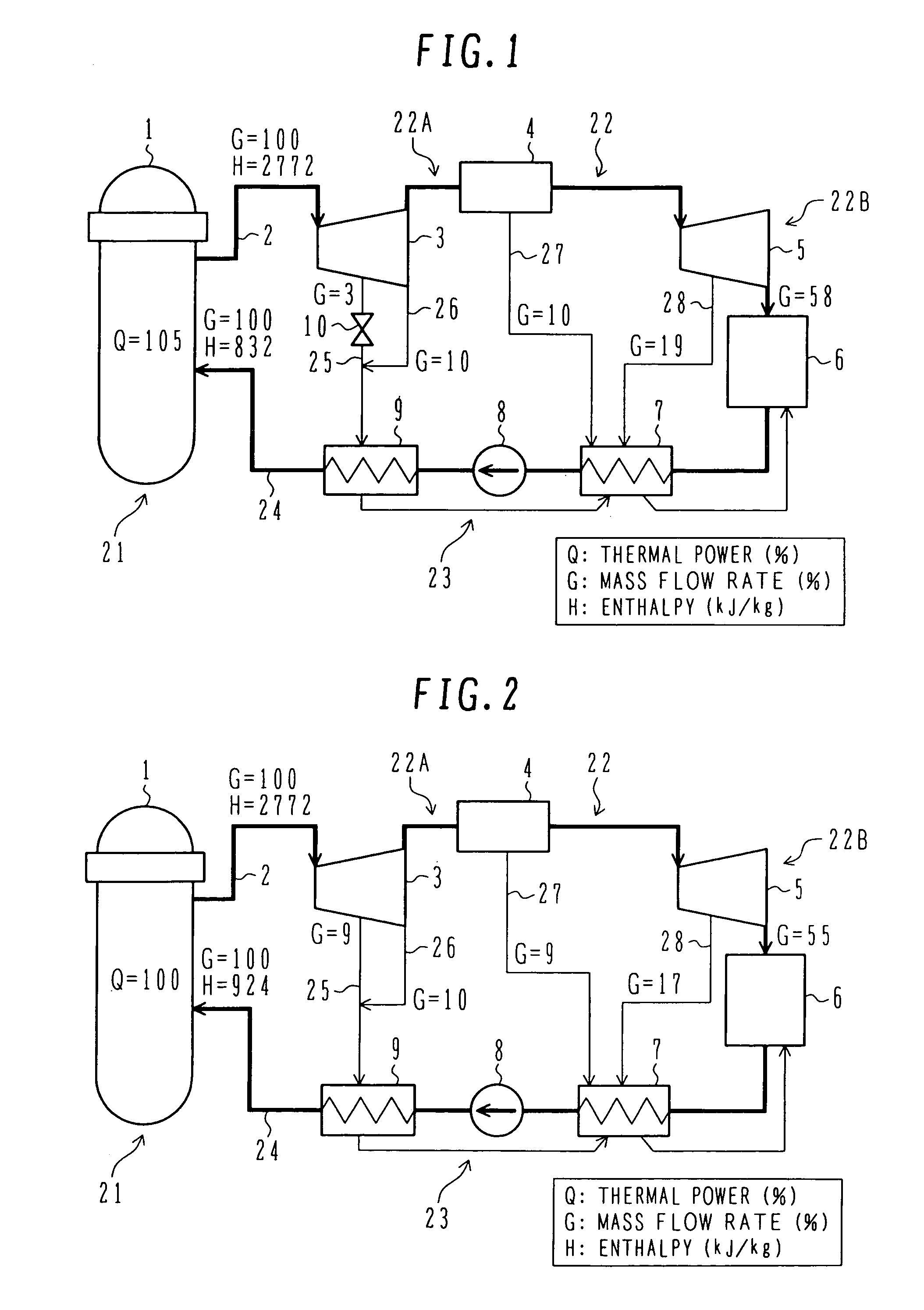
[0042]The overall construction of the boiling water reactor system according to this embodiment will be first described with reference to FIG. 1.

[0043]In FIG. 1, reference numeral 1 denotes a reactor pressure vessel. Recirculation pumps and jet pumps are installed outside and inside the reactor pressure vessel 1 to regulate the rate of flow passing through a core (i.e., a core flow rate). The reactor pressure vessel 1 and its internals constitute a reactor 21, and steam generated in the reactor 21 is supplied to a steam system 22. The steam system 22 comprises a main steam line 2, a high pressure turbine 3 and a low pressure turbine 5 connected to the main steam line 2 in series, and a moisture separator 4 disposed between the high pressure turbine 3 and the low pressure turbine 5. A section including the high pressure turbine 3, which ...

second embodiment

[0071]Another embodiment of the present invention in which the invention is applied to the boiling water reactor power plant as one of nuclear power plants will be described below with reference to FIGS. 8 and 9. The same components as those in the first embodiment are denoted by the same numerals.

[0072]As in the first embodiment, he boiling water reactor power plant of this embodiment comprises a reactor pressure vessel 1, a main steam line 2, a high pressure turbine 3 and a low pressure turbine 5 connected to the main steam line 2 in series, and a moisture separator 4 (or a moisture separator and heater) disposed in the main steam line 2 between the high pressure turbine 3 and the low pressure turbine 5. A low pressure feedwater heater 7, a feedwater pump 8, and a high pressure feedwater heater 9 are installed in a feedwater system 23 downstream of a condenser 6.

[0073]When the reactor thermal power is uprated, the flow rate of the feedwater has to be increased or the enthalpy diff...

third embodiment

[0079]A boiling water reactor power plant according to still another embodiment (third embodiment) of the present invention will be described below with reference to FIG. 10.

[0080]This third embodiment differs from the second embodiment in that, instead of the feedwater temperature sensor 39, an extraction flowmeter 44 is disposed in the extraction line 25 in which the extracted flow control valve 38 is disposed. The extracted flow controller 40 receives a measured value from the extraction flowmeter 44 and a set value of the flow rate of the extracted steam. The extraction flowmeter 44 measures the flow rate of the extracted steam supplied to the high pressure feedwater heater 9. The extracted flow control valve 38 and the extraction flowmeter 44 may be disposed in the extraction line 25 irrespective of which one of them is positioned upstream of the other. When the extraction line 25 is merged midway with another extraction line (e.g., the extraction line 26), one of the extracted...


PUM


Abstract

In a nuclear power plant, thermal power in a second operation cycle of a nuclear reactor is uprated from thermal power in a first operation cycle preceding the second operation cycle by at least one operation cycle. A proportion of steam extracted from a steam system and introduced to a feedwater heater, which is in particular extracted from an intermediate point and an outlet of a high pressure turbine, with respect to a flow rate of main steam, is reduced in the second operation cycle from that in the first operation cycle such that the temperature of feedwater discharged from the feedwater heater is lowered by 1° C. to 40° C. in the second operation cycle.

Description

BACKGROUND OF THE INVENTION[0001]1. Field of the Invention[0002]The present invention relates to an operation method of a nuclear power plant and to a nuclear power plant. More particularly, the present invention relates to an operation method of a nuclear power plant and to a nuclear power plant, which are suitable for an uprate of normal operation power output of a nuclear power plant.[0003]2. Description of the Related Art[0004]In a newly constructed nuclear power plant, electric power has hitherto been uprated, for example, by improving the fuel makeup or the shape and makeup of a fuel assembly so as to increase the flow rate of main steam at a core outlet.[0005]Such related art is disclosed in Patent Document 1 (JP,A 9-264983).SUMMARY OF THE INVENTION[0006]When the above-mentioned related art is applied to the existing nuclear power plant, the rate of core flow passing through a reactor core is substantially the same as that before the power uprate, while thermal power of the c...

Claims


Application Information

Patent Timeline
Patent Type & Authority Patents(United States)
IPC IPC(8): G21D5/00
CPCG21C1/084G21D1/02G21D3/00G21Y2002/201Y02E30/39G21Y2004/30G21Y2004/40Y02E30/31G21Y2002/304Y02E30/30Y02E30/00
Inventor CHAKI, MASAOKITOU, KAZUAKIAOYAMA, MOTOOOOTSUKA, MASAYASHIINA, KOUJI
Owner HITACHI-GE NUCLEAR ENERGY LTD
Why Eureka
Try Eureka