Ceiling mount

a technology for mounting brackets and ceilings, applied in the field of ceiling mounts, can solve the problems of wasting money and too much time in fixing mounts

Active Publication Date: 2009-12-08
VTC ELECTRONICS
View PDF15 Cites 39 Cited by
  • Summary
  • Abstract
  • Description
  • Claims
  • Application Information

AI Technical Summary

Benefits of technology

[0009]Other objects, advantages and novel features of the invention will become more apparent from the following detailed description when taken in conjunction with the accompanying drawings.

Problems solved by technology

Therefore, it is noted that the installation process of the fixing mount is too time consuming and inappropriate in that when the thickness of the ceiling is various from one another, the operator will have to purchase a different ceiling mount to adapt for this different ceiling thickness, which is still, a waste of money.

Method used


Image

  • Ceiling mount
  • Ceiling mount
  • Ceiling mount

Examples


Embodiment Construction

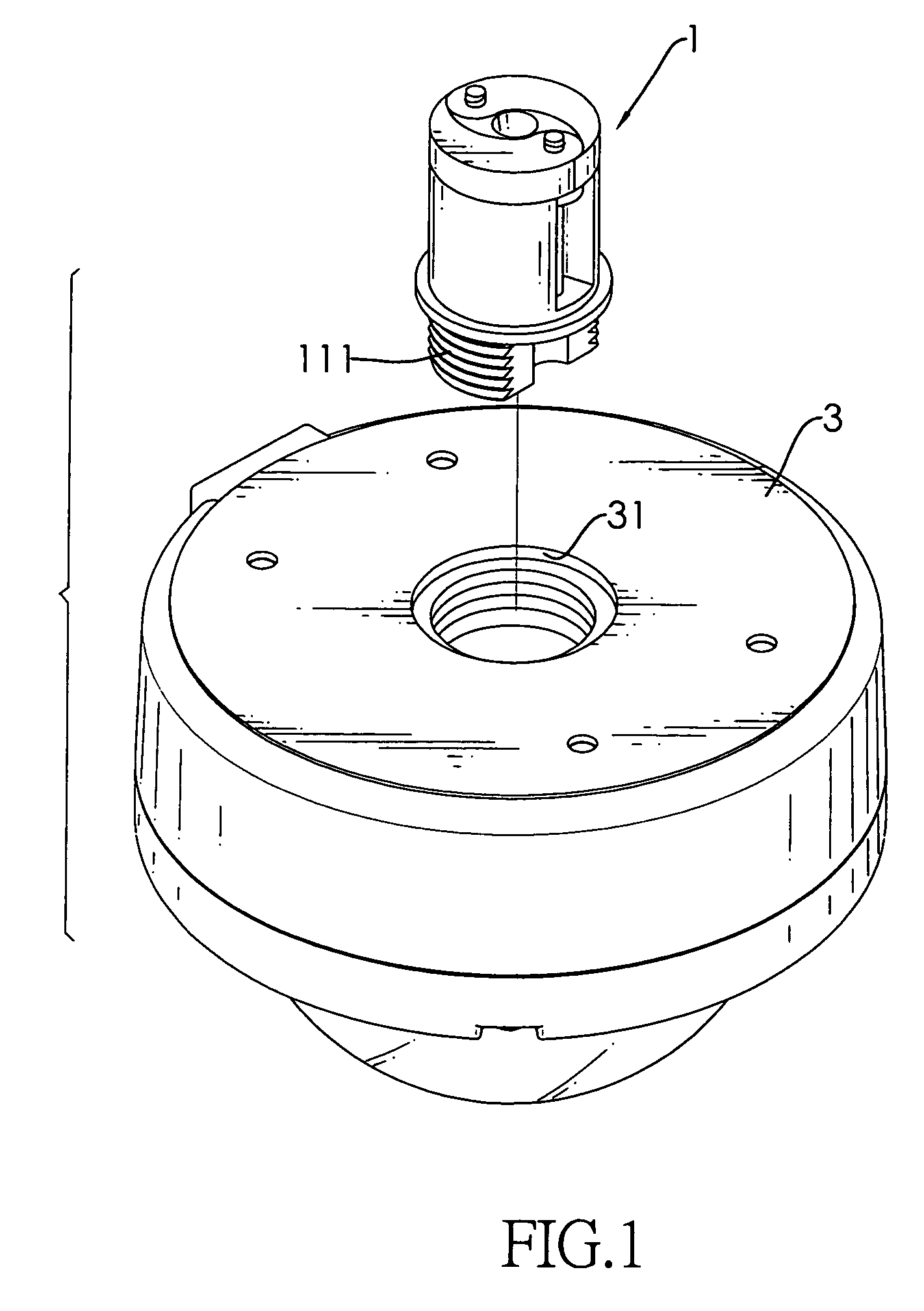
[0017]With reference to FIG. 1, it is noted that the ceiling mount in accordance with the present invention includes a core (1) and a base (3). The base (3) is provided with a threaded hole (31) defined through a face of the base (3) to mesh with an outer threading (111) extending from the bottom of the core (1) such that the core (1) is able to detachably engage and combine with the base (3).

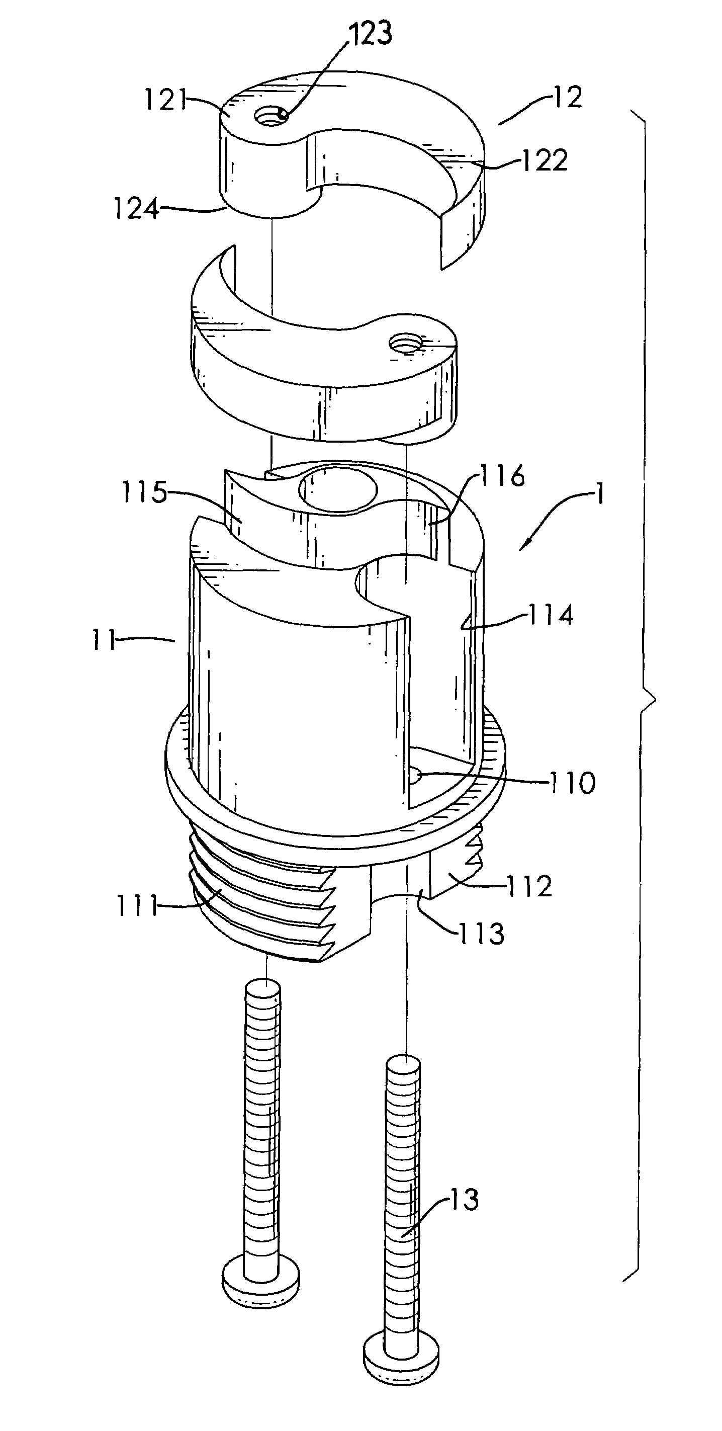
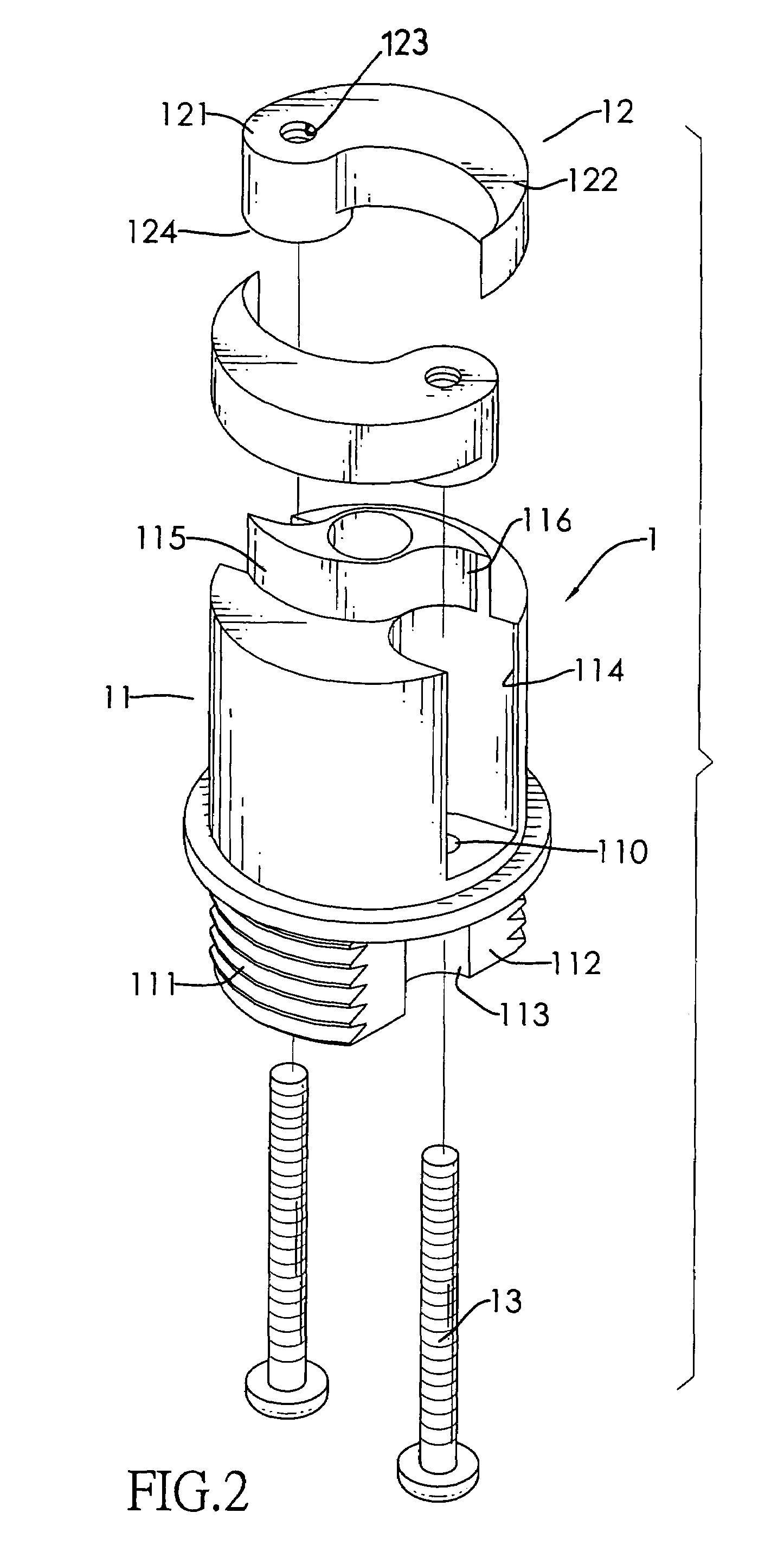
[0018]With reference to FIG. 2, it is noted that the core (1) of the present invention is composed of a cylindrical body (11) having the bottom extension formed at a lower portion of the cylindrical body (11), two arms (12) and two threaded bolts (13).

[0019]The cylindrical body (11) further has two cutouts (112) defined in two opposed sides of the bottom extension and a sectorial passage (113) is defined in a bottom face of each of the cutouts (112) to communicate with the cutouts (112) respectively. Two indentations (114) are oppositely defined in an outer periphery of the cylindrical body (11...


PUM


Abstract

A ceiling mount includes a base adapted to engage with one side of the ceiling, a core extending through the base to securely connect to the base and having a cylindrical body provided with at least one indentation, at least one arm selectively extending out of and movably received in the at least one indentation of the cylindrical body for engagement with the other side of the ceiling so as to provide a supporting force, at least one threaded bolt rotatably mounted in the cylindrical body and operably connected to the at least one arm to allow the at least one arm to extend out of and move relative to the cylindrical body in response to the rotational movement of the at least one threaded bolt and a stop to avoid the at least one arm from further extending.

Description

BACKGROUND OF THE INVENTION[0001]1. Field of the Invention[0002]The present invention relates to a ceiling mount, and more particularly to ceiling mount having two wings selectively extending outward from a central rod to abut a face of a ceiling so as to support a load attached to a base of the central rod.[0003]2. Description of the Prior Art[0004]During renovation or decoration of a building, a ceiling light is the most popular object to be chosen to enhance the soft touches to the building. For its easy installation and maintenance, a lot of ceiling lights are used in modern constructions. While mounting the ceiling light, a fixing mount is required to support the load of the ceiling light such that the operator is able to readily adjust the angle of the ceiling light. Other than the ceiling light, lighting instruments of different kinds to be mounted on the ceiling also require a fixing mount so as to support the load of the lighting instruments. Other applications such as the ...

Claims


Application Information

Patent Timeline
Patent Type & Authority Patents(United States)
IPC IPC(8): B42F13/00
CPCF21V21/04F16B13/0808F16B13/04F21V21/03
Inventor SCOTT, CRAIG CAMERON
Owner VTC ELECTRONICS
Why Eureka
Try Eureka