Worm wheel and worm gear

a technology of worm gear and die-cutting worm wheel, which is applied in the direction of gearing, gearing elements, hoisting equipment, etc., can solve the problems of inconvenient cutting work, inconvenient die-cutting of worm wheel, and inevitable increase of man-hours for connecting two members

Inactive Publication Date: 2010-01-05
AISIN SEIKI KK
View PDF9 Cites 18 Cited by
  • Summary
  • Abstract
  • Description
  • Claims
  • Application Information

AI Technical Summary

Benefits of technology

[0008]According to an aspect of the present invention, a resin worm wheel is formed by injection molding and includes a first end and a second end. The worm wheel is adapted to be driven by a worm. The worm wheel further includes: an engaging portion including a plurality of teeth engageable with the worm and a tooth space formed between the neighboring teeth; a first non-engaging portion adjacent to the engaging portion at the first end of the worm wheel and not engaging with the worm; and a first cutout portion formed at the first non-engaging portion continuously from the tooth space. The first cutout portion extends axially.

Problems solved by technology

If the amount of the undercut is large, it may be difficult to die-cut the worm wheel after molding the worm wheel in the die, which structures the worm wheel disclosed in this reference with two members.
The worm wheel disclosed in the reference needs to be structured by resin-molding two members separately and by bonding the two members perpendicularly along the axis direction, thus leading to an inevitable increase of man-hours to connect two members.
However, the cutting work is not cost efficient and a certain improvement is considered to be necessary for this method from the viewpoint of productivity.

Method used


Image

  • Worm wheel and worm gear
  • Worm wheel and worm gear
  • Worm wheel and worm gear

Examples


Embodiment Construction

[0016]Embodiments of the present invention will be descried below with reference to the attached drawing figures.

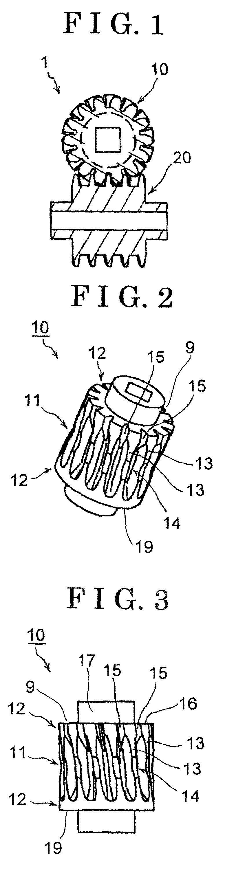
[0017]FIG. 1 is a view illustrating a worm gear 1, which serves as a worm speed reducer, including a worm wheel 10 related to a first embodiment of the present invention. The worm gear 1 includes the worm wheel 10 and a worm 20. The worm wheel 10 is engaged with the worm 20 and is driven thereby. The worm wheel 10 includes a first end 9 and a second end 19 in an axial direction thereof.

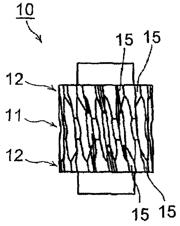
[0018]FIG. 2 is a perspective view of the worm wheel 10 and FIG. 3 is a front view of the worm wheel 10. The entire body of the worm wheel 10 is formed in one operation by injection molding. The worm wheel 10 is provided with an engaging portion 11 and non-engaging portion 12 which serve as a first non-engaging portion and a second non-engaging portion. The engaging portion 11 is formed at the axially middle portion of the worm wheel 10, i.e., in an up and down direction in FIG. 3. The enga...


PUM


Abstract

A resin worm wheel is formed by injection molding and includes a first end and a second end. The worm wheel is adapted to be driven by a worm. The worm wheel further includes: an engaging portion including a plurality of teeth engageable with the worm and a tooth space formed between the neighboring teeth; a first non-engaging portion adjacent to the engaging portion at the first end of the worm wheel and not engaging with the worm; and a first cutout portion formed at the first non-engaging portion continuously from the tooth space, the first cutout portion extending axially.

Description

CROSS REFERENCE TO RELATED APPLICATIONS[0001]This application is based on and claims priority under 35 U.S.C. § 119 to Japanese Patent Application 2006-176515, filed on Jun. 27, 2006, the entire content of which is incorporated herein by reference.FIELD OF THE INVENTION[0002]This invention relates to a resin-made worm wheel driven by a worm and a worm gear (worm speed reducer) having the same.BACKGROUND[0003]A known worm wheel is disclosed in JP2002-310267A (hereinafter, refers to as a reference. The worm wheel is formed with resin and driven by a worm. The worm wheel is provided with: an engaging portion having a plurality of teeth engaged with the worm; and tooth spaces defined between the neighboring teeth and of which bottom surface is recessed radially inwardly. The worm wheel is structured by integrating two members divided perpendicularly to the axis thereof.[0004]Generally at a resin molding with a die, undercut is formed by tooth spaces when the bottom surfaces of each toot...

Claims


Application Information

Patent Timeline
Patent Type & Authority Patents(United States)
IPC IPC(8): F16H55/22
CPCF16H55/22F16H55/06F16H2055/065Y10T74/19828Y10T74/19953Y10T74/19949Y10T74/19633
Inventor SUZUKI, YASUAKITAKEDA, NOBUHIKOHIRAO, KOUJI
Owner AISIN SEIKI KK
Why Eureka
Try Eureka