System and method for delivering a bifurcated stent

a technology of bifurcated stents and loop structures, applied in the field of stents, can solve the problems of significant delay in the procedure, catheters are positively stopped at that position, and cannot be advanced any further along the guide wires, so as to eliminate any possible confusion, reduce the risk of complications, and improve the effect of vascular vascular vascular vascular vascular vascular vascular vascular vascular vascular vascular vascular vascular vascular vascular vascular vascular vascular vascular vascular vascular vascular

Inactive Publication Date: 2010-01-05
MEDINOL LTD
View PDF106 Cites 32 Cited by
  • Summary
  • Abstract
  • Description
  • Claims
  • Application Information

AI Technical Summary

Benefits of technology

[0010]Embodiments of the present invention solves these and other disadvantages of the prior art by providing a side branch balloon catheter whose tip leads the tip of the main vessel balloon catheter by few millimeters, so that the side branch balloon leads the delivery system while advancing towards the target area. The side branch balloon catheter reaches the target area first, allowing for greater freedom of the side branch balloon to bend into the aperture of the side branch vessel, due to less crowding of balloon catheter in the main vessel.
[0011]Another embodiment of the present invention provides a bifurcated stent delivery system having one over the wire catheter and one fixed wire catheter. This system only requires one guide wire and, therefore, eliminates any possible confusion that may result from wire crossing in the vasculature. The use of a single guide wire in this system also eliminates the possibility of wire crossings that result in the catheters becoming positively stopped at and unable to be advanced beyond the location of the wire crossing. In addition, since the fixed wire catheter does not include a guide wire lumen and thus has a smaller profile than an over-the-wire catheter, this system provides a smaller combined profile which enables the system to pass through more severe constrictions in the vasculature when the catheters are advanced to the target site together.

Problems solved by technology

One disadvantage of this bifurcating stent is the complex nature of the interconnection of the flexible wires forming the backbones with the loop structure of each lattice.
The use of two “over-the-wire” catheters with separate guide wires can result in wire crossings within the vasculature which may create confusion to the physician as to which of the guide wires leads to the main vessel and which of the guide wires leads to the side branch lumen.
This can result in a significant delay in the procedure.
However, the most serious problem resulting from such wire crossings occurs during the advancement of the two “over-the-wire” catheters on the wires.
Specifically, when the two catheters reach the point of a wire crossing, the catheters are positively stopped at that position and cannot be advanced any further along the guide wires.
This is both risky and time consuming.
Upon reaching the target area in the vessel, the main vessel becomes very crowded due to both balloons filling up the lumen of the main vessel.
This causes the tip of the side branch balloon to be pressed against the main vessel, and causes difficulty in orienting the balloon into the side branch lumen, and hinders the ability of the side branch balloon to bend into the side branch vessel.

Method used


Image

  • System and method for delivering a bifurcated stent
  • System and method for delivering a bifurcated stent
  • System and method for delivering a bifurcated stent

Examples


Embodiment Construction

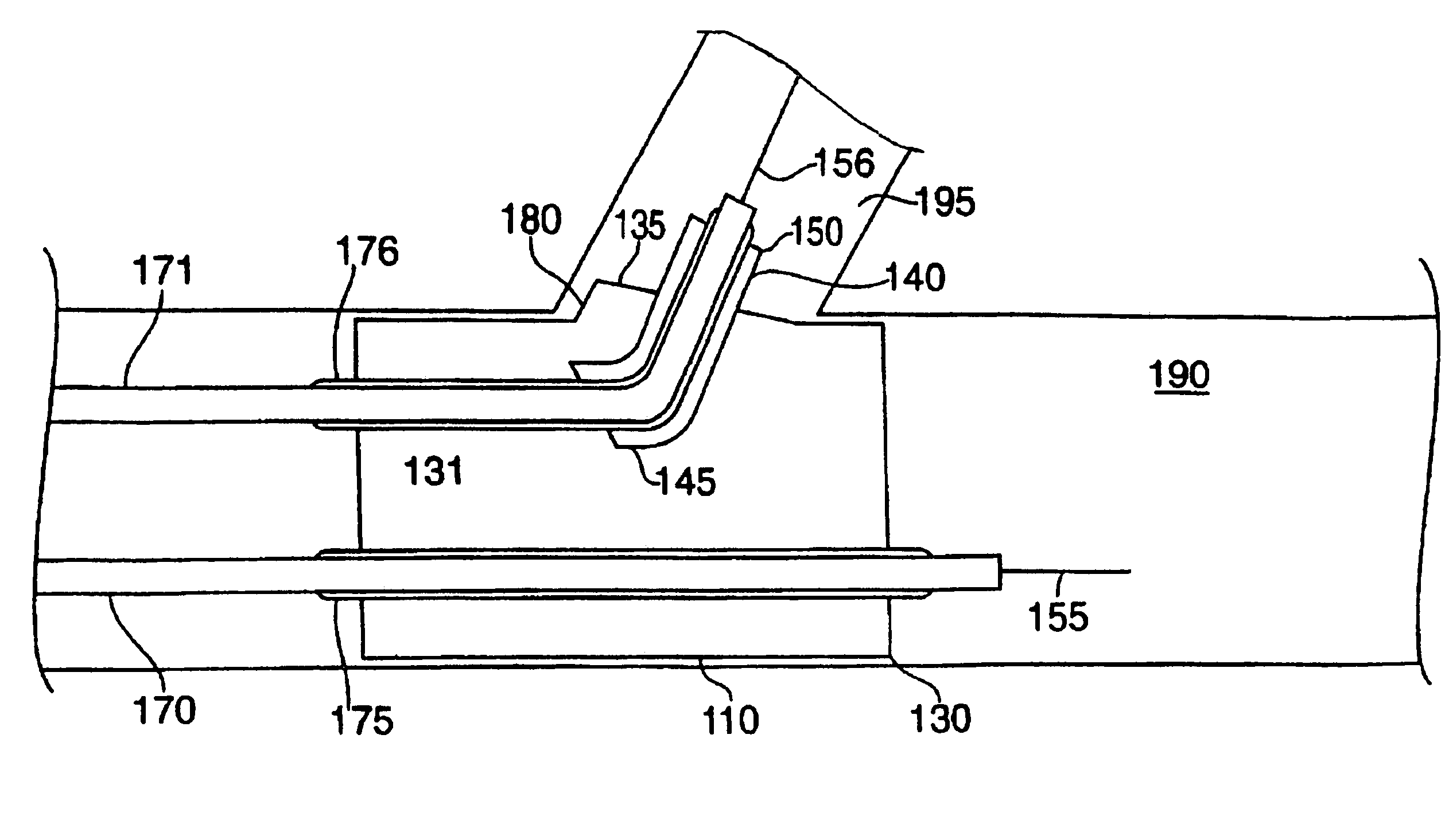
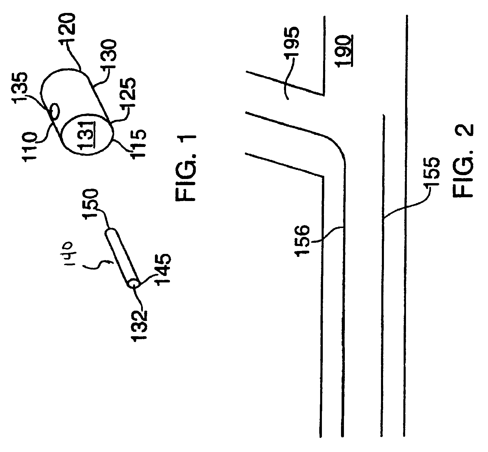
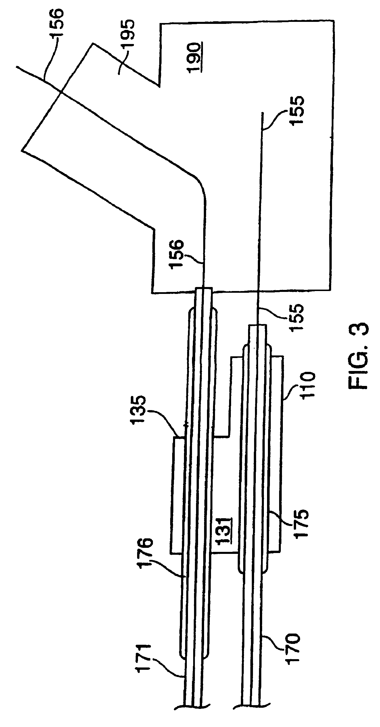
[0029]FIG. 1 is a general representation of one type of a stent with which the present invention may be used. The stent comprises two portions, which are deployed serially in two steps and assembled within the patient to form a bifurcated stent. FIG. 1 shows stem and first leg portion 110 provided with a longitudinal bore 131 and having a proximal end 115 defining a stem portion 125 and a distal end 120. Second leg portion 140 is provided with a longitudinal bore 132 and has a proximal end 145 and a distal end 150. Stem and first leg portion 110 and second leg portion 140 may be sized and patterned or etched as previously discussed. A branch aperture 135 is disposed between the proximal end 115 and the distal end 120 of stem and first leg portion 110. The branch aperture 135 is sized to receive second leg portion 140 and is adapted to engage and secure the second leg portion 140 when it has been expanded within the branch aperture 135. Second leg portion 140 is sized and adapted to ...


PUM


Abstract

A system and method for delivering and assembling a bifurcated stent in a bifurcated vessel having a first lumen and a second lumen. The system and method includes the use of three balloon catheters wherein at least one of the catheters is a fixed wire catheter. A first segment of the bifurcated stent having a stem portion, a first leg portion, a longitudinal bore extending therethrough and a branch aperture formed in the side wall is mounted on two of the balloon catheters and delivered to the treatment site where it is implanted into the first lumen. A second segment of the bifurcated stent having a proximal end, a distal end and a longitudinal bore extending therethrough is mounted on the third balloon catheter and is delivered to the treatment site such that the distal end extends into the second lumen and the proximal end extends into longitudinal bore of the first segment. The second segment is then implanted into the second lumen and secured to the branch aperture of the first segment to form a bifurcated stent.

Description

CROSS-REFERENCE TO RELATED APPLICATIONS[0001]This application is a continuation-in-part of application Ser. No. 11 / 339,317, filed Jan. 24, 2006, now U.S. Pat. No. 7,371,255, which is a continuation of application Ser. No. 10 / 066,755, filed Feb. 6, 2002, now U.S. Pat. No. 6,989,026, which is a division of application Ser. No. 09 / 575,957 filed May 23, 2000, now U.S. Pat. No. 6,440,165, which is a continuation-in-part of application Ser. No. 09 / 072,846, filed May 5, 1998, now U.S. Pat. No. 6,251,133, which is a continuation-in-part of application Ser. No. 09 / 049,842, filed Mar. 27, 1998, now U.S. Pat. No. 6,090,133, which is continuation of application Ser. No. 08 / 840,612, filed on Apr. 29, 1997, now U.S. Pat. No. 5,755,734, which is a division of application Ser. No. 08 / 642,297, filed May 3, 1996, now abandoned.FIELD OF THE INVENTION[0002]The present invention relates to stents, and more particularly methods of delivering a bifurcated stent.BACKGROUND OF THE INVENTION[0003]Stents are ...

Claims


Application Information

Patent Timeline
Patent Type & Authority Patents(United States)
IPC IPC(8): A61F2/06A61F2/82
CPCA61F2/07A61F2/82A61F2/954A61F2/958A61F2/856A61F2230/001
Inventor RICHTER, JACOB
Owner MEDINOL LTD
Why Eureka
Try Eureka