Transient energy systems and methods for use of the same

Active Publication Date: 2010-01-05
P10 IND INC
View PDF53 Cites 13 Cited by
  • Summary
  • Abstract
  • Description
  • Claims
  • Application Information

AI Technical Summary

Benefits of technology

[0024]In an embodiment of the invention, a coil spring may be built into the bottom bearing housing assembly to apply an upward preload force to the bearing contained therein. This upward force counteracts a predetermined portion of the downward force exerted by the flywheel and any other component of the rotor assembly which may contribute to the downward force exerted on the bearing. As a result of the upward preload force, the loading on the lower bearing is reduced, thereby increasing the life of the bearing. If desired, the upward preload force may be such that the load seen by both the upper and lower bearings is approximately equal.
[0025]In another embodiment for reducing bearing loading, the magnetic center of the rotor circuitry is offset in a vertical direction with respect to the magnetic center of the stator circuitry to generate an axial force (in either an upward or downward direction depending on the direction of the vertical offset) when the induction motor/generator is operating in a motoring mode. This axial force may reduce the load seen by, for example, the lower bearing, thereby increasing its operational life.
[0026]The flywheel energy storage system is optimized for transient power generation by reducing the physical size, standby power consumption, and inductance of the induction motor/generator, as compared to other induction motor/generators of comparable size. Smaller size generally correlates to less cost. Reduced standby power consumption saves energy cost and heat losses and reduced inductance enables the flywheel system to quickly switch from a motoring mode to a generating mode.
[0027]An advantage of the flywhe

Problems solved by technology

Batteries have poor reliability, are bulky (thus requiring substantial storage space), are expensive to maintain, and contain environmentally damaging chemicals.
Ultra-capacitors are expensive and their development has yet to achieve economies of scale which would permit their widespread use.
A disadvantage of such flywheel systems is that they become relatively large (thereby occupying substantial floor space), heavy and costly, in applications where longer runtimes are desired.
Because interruptions in the supply of power from a primary power source are relatively rare, the need for transient systems to supply power on demand may occur only a few times during the life of such systems.
However, when backup po

Method used


Image

  • Transient energy systems and methods for use of the same
  • Transient energy systems and methods for use of the same
  • Transient energy systems and methods for use of the same

Examples


Example

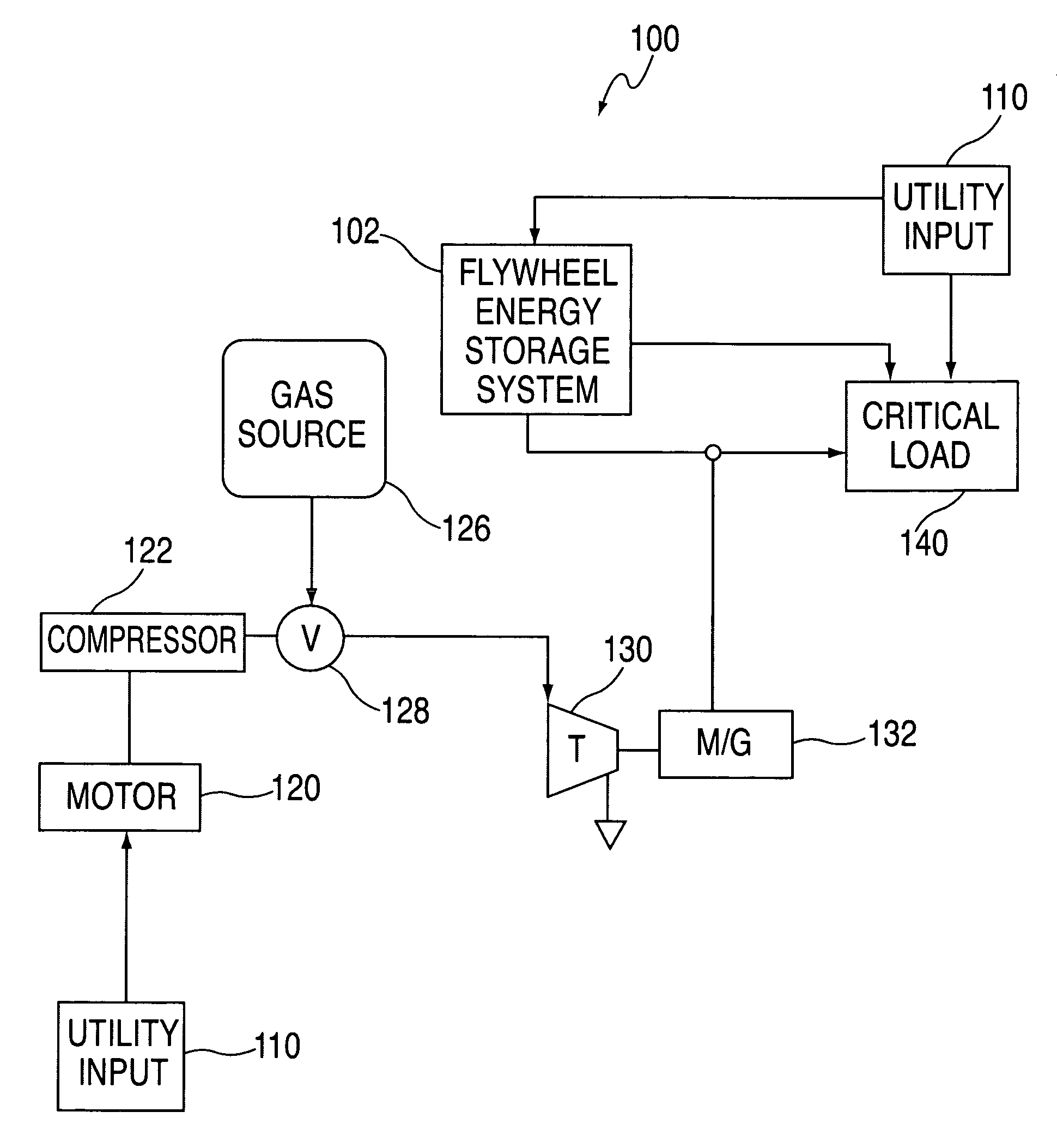
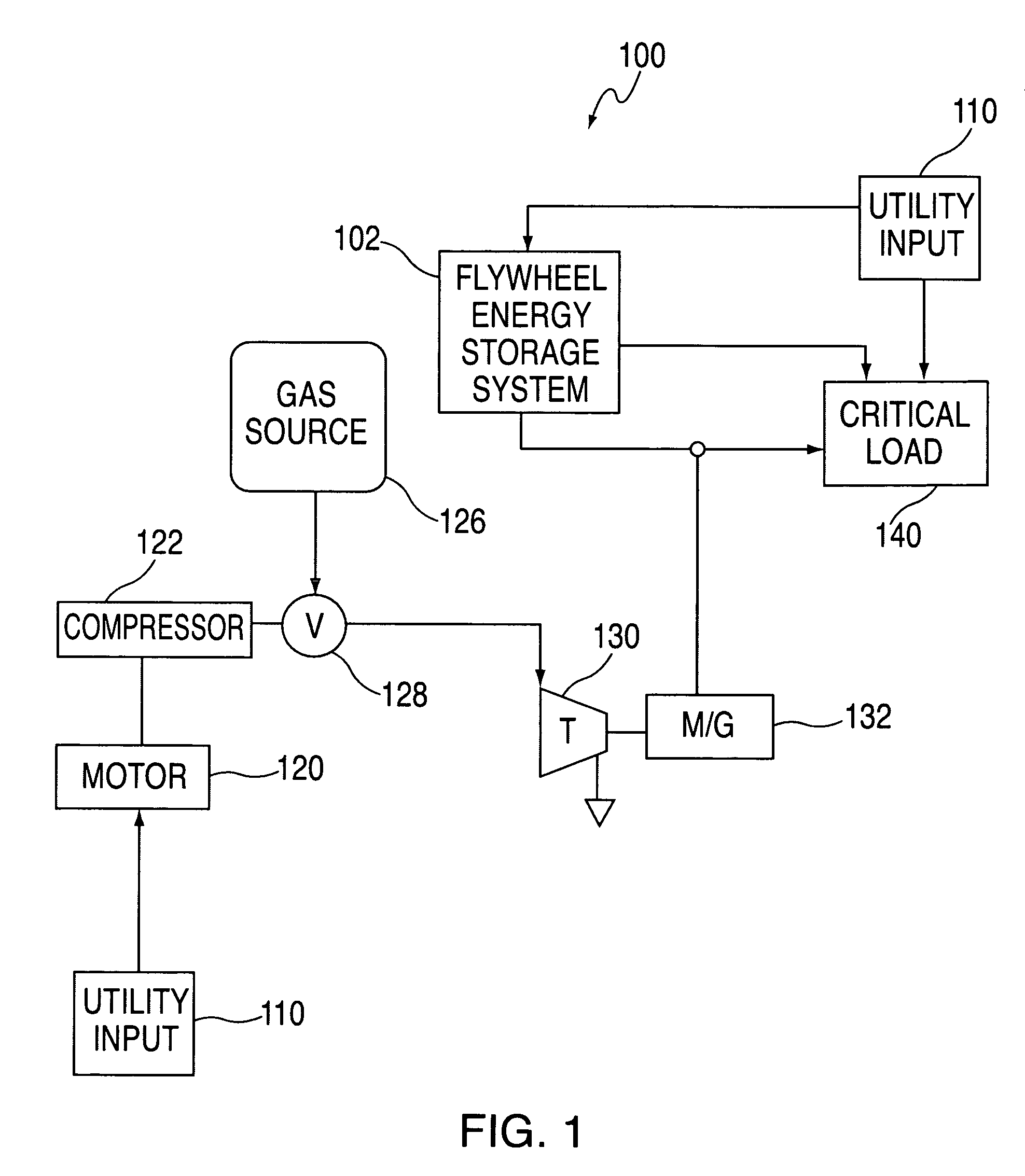
[0053]FIG. 1 shows a block diagram of a compressed air storage (CAS) backup energy system 100, including a flywheel energy storage system in accordance with the present invention, for providing backup power to a load. Backup energy system 100 includes utility input 110 which supplies power to critical load 140 during normal operating conditions. Persons skilled in the art will appreciate that utility input 110 may be any suitable type of primary power source. As illustrated in FIG. 1, backup energy system 100 includes a flywheel energy system 102 according to the principles of the present invention integrated with the components of a CAS system in order to provide backup power to critical load 140. Backup energy system 100 includes motor 120, compressor 122, gas source 126 (e.g., pressure tank), valve 128, turbine 130 and electrical machine 132.

[0054]During normal operating conditions, utility input 110 supplies critical load 140 with power. Utility power 110 also provides bridging ...


PUM


Abstract

This disclosure relates to transient energy systems for supplying power to a load substantially instantaneously on demand. Transient energy systems may include a flywheel coupled the rotor of an induction motor generator. One embodiment of the disclosure refers to systems and methods for reducing loads on a bearing in a transient energy system. In another embodiment, the disclosure refers to an induction motor generator that is optimized for high power transient power generation, yet low power motor operation. Yet another embodiment of the disclosure refers to using a flywheel as a drag pump to cool components of a transient energy system. In yet another embodiment, a slip control scheme is discussed for regulating a DC bus. In yet a further embodiment of the disclosure a method is provided for reducing unnecessary turbine starts by making turbine start a function of the rotational velocity of a flywheel.

Description

BACKGROUND OF THE DISCLOSURE[0001]This relates to transient energy systems for supplying power to a load substantially instantaneously on demand. More particularly, this relates to flywheel energy storage systems constructed with an induction motor-generator.[0002]There are many different types of transient systems, including, for example, batteries, ultra-capacitors, and flywheel energy storage systems, all of which are capable of providing power substantially immediately on demand. Batteries have poor reliability, are bulky (thus requiring substantial storage space), are expensive to maintain, and contain environmentally damaging chemicals. Ultra-capacitors are expensive and their development has yet to achieve economies of scale which would permit their widespread use. An example of a flywheel energy storage system includes the relatively high mass flywheel type of system. In this type of flywheel energy system, the flywheel is contained in an airtight container under vacuum to r...

Claims


Application Information

Patent Timeline
IPC IPC(8): H02P9/04
CPCH02J3/30H02P9/46Y02E60/16
Inventor ANDREWS, JAMES AHUDSON, ROBERT S.
Owner P10 IND INC
Why Eureka
Try Eureka